DEMO9S08QE32 Freescale Semiconductor, DEMO9S08QE32 Datasheet - Page 2
DEMO9S08QE32
Manufacturer Part Number
DEMO9S08QE32
Description
DEMO FOR S08 AND QE32/16
Manufacturer
Freescale Semiconductor
Series
Flexis™r
Type
MCUr
Datasheets
1.DC9S08QE32.pdf
(7 pages)
2.DC9S08QE32.pdf
(41 pages)
3.DEMO9S08QE32.pdf
(2 pages)
4.DEMO9S08QE32.pdf
(3 pages)
Specifications of DEMO9S08QE32
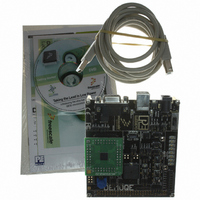
Contents
Board, Cable, CD
Processor To Be Evaluated
MC9S08QE32
Data Bus Width
8 bit
Interface Type
RS-232, USB
Silicon Manufacturer
Freescale
Core Architecture
HCS08
Core Sub-architecture
HCS08
Silicon Core Number
MC9S08
Silicon Family Name
Flexis - S08QE
Kit Contents
Board
Rohs Compliant
Yes
For Use With/related Products
MC9S08QE32
For Use With
DEMOACEX - BOARD EXPANSION FOR DEMO KIT
Lead Free Status / RoHS Status
Lead free / RoHS Compliant


DEMO9S08Q32—Lab Tutorials
Taking the Lead in Low Power
About
DEMO9S08QE32 Labs
These labs will show you how to get the
most out of your DEMOQE toolkit. Start
each lab with the board powered ON.
Make sure to use only one utility at a
time, as they share the same USB source.
Familiarize yourself with these buttons:
Start/Continue (F5) button
MCU Change Wizard button
Debug button
Learn How to Use
DEMOQE Toolkit Utilities
This lab will show you how to use one of several
graphical utilities in the DEMOQE Toolkit included
with your board. Instructions to download these
utilities to your computer are provided in Step 2 of
the Quick Start Guide (DEMOS08QE32QSG.pdf).
Running the Quick Start Application that came pre-
loaded in the microcontroller’s on-chip flash memory,
we will now use the DEMOQE Logic Analyzer utility.
This PC-based utility graphs the IN0 and IN1 signals
on the board. For convenience, if both J11 jumpers
are installed, IN0 graphs PTC0 activity and IN1 graphs
PTC1 activity. To graph other microcontroller signals,
use wire jumpers from IN0 and IN1 to the respective
signals on the board’s MCU PORT.
1. Make sure that the Quick Start Application is running.
2. Launch DEMOQE Logic Analyzer utility from the start
3. In utility, click on the “Open DEMOQE and Graph Pins”
4. Click button labeled “PTA2.” This will cause a fixed duty
5. Rotate the potentiometer W1. This will change the duty
6. Click on “Close Port” button when finished.
For more information on DEMOQE Toolkit, read the
board user manual (DEMO9S08QE32UM.pdf) included
on DVD under “DEMO9S08QE32
User Manual.” For new and upgraded utilities to the
DEMOQE Toolkit, visit www.pemicro.com/fixedlinks/
demoQEtoolkit.html
LAB
menu (Programs
>
Manual for details on the Logic Analyzer Utility.
button to begin graphing IN0 and IN1. These signals will
be continually graphed at a sampling rate of 10 kHz.
cycle pulse width modulation signal to be output on the PTC0
pin. The PTC0 waveform is shown on analyzer channel IN0.
cycle of the variable pulse width modulation signal
output on the PTC1 pin. The PTC1 waveform is shown on
analyzer channel IN1.
1
Logic Analyzer Utility). *See DEMO9S08QE32 User
>
P&E DemoQE Toolkit
>
DEMO9S08QE32
>
Utilities
Barrel
connector for
external power
Embedded BDM
32.768k Crystal
DC9S08QE32
Daughter Card
Power select
Jumper (USB or
external)
Figure 1. DEMOQE baseboard with DC9S08QE32 daughter card.
AccelerometerDemo running on MC9S08QE32 in data
averaging mode. Bar graph ‘C’ highlights the bus cycles
required to average the last 16 readings of the 3 axes.
The value in the 4th column in the terminal window is the
number of bus cycles in hex.
LEDs
Push Button
RESET Button
MMA7260
Accelerometer
MCU Port
Potentiometer
Related parts for DEMO9S08QE32
Image
Part Number
Description
Manufacturer
Datasheet
Request
R

Part Number:
Description:
Manufacturer:
Freescale Semiconductor, Inc
Datasheet:
Part Number:
Description:
Manufacturer:
Freescale Semiconductor, Inc
Datasheet:
Part Number:
Description:
Manufacturer:
Freescale Semiconductor, Inc
Datasheet:
Part Number:
Description:
Manufacturer:
Freescale Semiconductor, Inc
Datasheet:
Part Number:
Description:
Manufacturer:
Freescale Semiconductor, Inc
Datasheet:
Part Number:
Description:
Manufacturer:
Freescale Semiconductor, Inc
Datasheet:
Part Number:
Description:
Manufacturer:
Freescale Semiconductor, Inc
Datasheet:
Part Number:
Description:
Manufacturer:
Freescale Semiconductor, Inc
Datasheet:
Part Number:
Description:
Manufacturer:
Freescale Semiconductor, Inc
Datasheet:
Part Number:
Description:
Manufacturer:
Freescale Semiconductor, Inc
Datasheet:
Part Number:
Description:
Manufacturer:
Freescale Semiconductor, Inc
Datasheet:
Part Number:
Description:
Manufacturer:
Freescale Semiconductor, Inc
Datasheet:
Part Number:
Description:
Manufacturer:
Freescale Semiconductor, Inc
Datasheet:
Part Number:
Description:
Manufacturer:
Freescale Semiconductor, Inc
Datasheet:
Part Number:
Description:
Manufacturer:
Freescale Semiconductor, Inc
Datasheet: