TWR-S08LH64 Freescale Semiconductor, TWR-S08LH64 Datasheet - Page 2
TWR-S08LH64
Manufacturer Part Number
TWR-S08LH64
Description
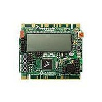
TOWER SYSTEM S08LH64
Manufacturer
Freescale Semiconductor
Type
MCUr
Datasheets
1.TWR-SENSOR-PAK.pdf
(4 pages)
2.TWR-S08LH64.pdf
(2 pages)
3.TWR-S08LH64.pdf
(19 pages)
4.TWR-S08LH64.pdf
(8 pages)
5.TWR-S08LH64.pdf
(3 pages)
Specifications of TWR-S08LH64
Contents
Board
Description/function
Tower System LCD Module
Interface Type
USB
Backlighting
No Backlighting
Data Bus Width
8 bit
Module Size (w X H X T)
3.55 in x 3.2 in
Number Of Segments
2 x 28
Operating Supply Voltage
5 V
Operating Voltage
3.3 V
Product
Display Modules
Software
Software Included
Touch Panel
No Touch Panel
Silicon Manufacturer
Freescale
Core Architecture
HCS08
Core Sub-architecture
HCS08
Silicon Core Number
MC9S08
Silicon Family Name
S08LH
Kit Contents
Board, Cable, CD
Rohs Compliant
Yes
For Use With/related Products
Freescale Tower System
Lead Free Status / RoHS Status
Lead free / RoHS Compliant


TWR-S08LH64-KIT includes:
•
•
•
•
CodeWarrior Development Studio
for Microcontrollers v6.3
Complimentary** Special Edition CodeWarrior
Development Studio for Microcontrollers
is a suite of tools that supports software
development for Freescale’s 8-bit MCUs and
32-bit V1 ColdFire devices. Designers can
further accelerate application development
with the help of Processor Expert, an award-
winning rapid application development tool
integrated into the CodeWarrior tool suite.
Freescale, the Freescale logo, CodeWarrior, ColdFire and processor Expert are trademarks or registered trademarks of Freescale
Semiconductor, Inc. in the U.S. and other countries. All other product or service names are the property of their respective owners.
© Freescale Semiconductor, Inc. 2010
Document Number: MC9S08LH6436FS Rev 1
Package Options
Part Number
MC9S08LH64CLK
MC9S08LH64CLH
MC9S08LH36CLH
TOWER SYSTEM
TWR-S08LH64 stand-alone development
board
TWR-PROTO prototyping module provides
access to all signals on the tower system,
allowing for easy signal probing and circuit
prototyping
TWR-ELEV elevator modules that connect
the MCU board and prototyping module,
USB and Ethernet cables
Interactive DVD complete with tools,
lab supplements and other helpful resources
Flash arrays
Dual 32 KB
4 KB RAM
= 64 KB
BDM
TOD
Temp Ranges Package
-40°C to +85°C
-40°C to +85°C
-40°C to +85°C
8 x 36 = 288
LCD driver
S08 core
ACMP
COP
LVD
KBI
SPI
2 x 2 ch. 16-bit
10 ch.16-bit
80 LQFP
64 LQFP
64 LQFP
2 x SCI
VREF
ADC
TPM
ICS
I
software,
2
C
Features
LCD Driver and Internal Charge Pump
•
•
•
•
•
•
•
•
•
•
•
•
•
•
•
•
•
•
On-Chip Memory
Input/Output
System Protection
Peripherals
Timer- two 2-channel (TPM1 and TPM2), selectable input
capture, output compare, buffered-edge or center-aligned
PWM on each channel
Two serial communications interfaces (SCI) modules,
offering asynchronous communications, 13-bit break option,
flexible baud rate generator, double buffered transmit and
receive and optional HW parity checking and generation
39 general purpose input/output (GPIO), two
output-only pins
Eight keyboard interrupt (KBI) pins with
selectable polarity
Watchdog computer operating properly (COP) reset with
option to run from dedicated 1 kHz internal clock source or
bus clock
Low-voltage detection with reset or interrupt, selectable
trip points
Illegal op code and illegal address detection with reset
Flash block protection
Low-power blinking mode
Internal charge pump
Front plane (FP) and back plane (BP) re-assignments
Capable of running in STOP3 and STOP2 mode
LCD driver pins are muxed with GPIO and other functions
Up to 64 KB flash compromised of two separate arrays to
facilitate read/program/erase over full operating voltage
and temperature
1.8V to 3.6V RAM
Analog comparator with selectable interrupt on rising,
falling or either edge or comparator output, compare option
to fixed internal bandgap reference voltage, outputs can be
optionally routed to TPM module, operation in STOP3
Serial peripheral interface (SPI) module with full-duplex
or single-wire bidirectional, double-buffered transmit and
receive master or slave mode, MSB-first or LSB first shifting
I
master operation, programmable slave address, interrupt-
driven byte-by-byte data transfer and support for broadcast
mode and 10-bit addressing
2
C with up to 100 kbps with maximum bus loading, multi-
Learn more:
For current information about Freescale products and
documentation, please visit www.freescale.com/lcd
and www.freescale.com/tower.
Benefits
•
•
•
•
•
•
•
•
•
•
•
•
•
•
•
•
•
•
•
•
•
•
•
Two TPMs allow for two different time bases, with a total of eight
timer channels
Provides standard UART communications peripheral
Allows full-duplex, asynchronous NRZ serial communication between MCU
and remote devices
Edge interrupt can wake up MCU from low-power mode
Results in large number of flexible I/O pins that allow developers to easily
interface devices into their own designs
Can be used for reading input from a keypad or used as general
pin interrupts
Allows device to recognize runaway code (infinite loops) and resets processor
to avoid lock-up states
Warns the developer of voltage drops outside of the typical operating range
Allows the device to recognize erroneous code and resets the processor to
avoid lock-up states
Prevents unintentional programming of protected flash memory, which greatly
reduces the chance of losing vital system code for vendor applications
Low-power blinking mode does not require CPU intervention
Can be activated and CPU can go to sleep, but segments will remain blinking
at the pre-set frequency. Plus, an alternate display feature can be activated to
display alternate data (i.e., to blink temperature and time)
Provides option to run off a single supply a dual supply for sustained contrast
or a customized implementation of contrast control
FB and BP can be software selectable, making layout an easier task and very
flexible for design changes
Enables driving the display while the CPU sleeps, lowering the overall system
power consumption
Any LCD pin can be FP (segment) or BP (common), based on
software configuration
Allows you to take full advantage of operating voltage and temperature in-
application reprogrammability benefits in virtually any environment
Security circuitry prevents unauthorized access to RAM and flash contents,
reducing system power consumption
Requires only single pin for input signal, freeing additional pins for other use
Allows other components in system to see result of comparator with
minimal delay
Can be used for single-slope ADC and RC time-constant measurements
Allows high-speed (up to 5 Mbps) communications to other MCUs or
peripherals, such as MC1319x RF transceivers
I2C port enables increased system memory by using an additional I
EEPROM. This also creates an opportunity to add an additional I
2
C device
2
C
Related parts for TWR-S08LH64
Image
Part Number
Description
Manufacturer
Datasheet
Request
R

Part Number:
Description:
Development Boards & Kits - S08 / S12 S08PT60 Tower Kit
Manufacturer:
Freescale Semiconductor
Datasheet:
Part Number:
Description:
Development Boards & Kits - S08 / S12 S08PT60Tower MCU mod
Manufacturer:
Freescale Semiconductor
Datasheet:
Part Number:
Description:
TOWER UNIVERSAL RS08/S08
Manufacturer:
Freescale Semiconductor
Datasheet:
Part Number:
Description:
K53N512CMD100 TWR Module
Manufacturer:
Freescale Semiconductor
Datasheet:
Part Number:
Description:
TWR-K53N512 Dev Kit
Manufacturer:
Freescale Semiconductor
Datasheet:

Part Number:
Description:
CONV DC/DC TRI OUT 5,15,-15V
Manufacturer:
Murata Power Solutions Inc
Datasheet:

Part Number:
Description:
CONV DC/DC TRI OUT 5,12,-12V
Manufacturer:
Murata Power Solutions Inc
Datasheet:

Part Number:
Description:
CONV DC/DC TRI OUT 5,15,-15V
Manufacturer:
Murata Power Solutions Inc
Datasheet:

Part Number:
Description:
LCD MODULE FOR TWR SYSTEM
Manufacturer:
Freescale Semiconductor
Datasheet:

Part Number:
Description:
DC/DC TH 11W 5-5/12V Triple A
Manufacturer:
Murata Power Solutions Inc
Datasheet:


Part Number:
Description:
TOWER SYSTEM PROTO
Manufacturer:
Freescale Semiconductor
Datasheet:

Part Number:
Description:
TOWER ELEVATOR BOARDS HARDWARE
Manufacturer:
Freescale Semiconductor
Datasheet: