DEMO9S08QG8E Freescale Semiconductor, DEMO9S08QG8E Datasheet - Page 10
DEMO9S08QG8E
Manufacturer Part Number
DEMO9S08QG8E
Description
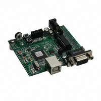
BOARD DEMO FOR MC9S08QG8
Manufacturer
Freescale Semiconductor
Type
MCUr
Specifications of DEMO9S08QG8E
Contents
Board
Processor To Be Evaluated
MC9S08QG8
Data Bus Width
8 bit
Interface Type
RS-232, USB
Silicon Manufacturer
Freescale
Core Architecture
HCS08
Core Sub-architecture
HCS08
Silicon Core Number
MC9S08
Silicon Family Name
S08QG
Kit Contents
MC9S08QG8 Board, Software, Cables, Connectors
Rohs Compliant
Yes
For Use With/related Products
MC9S08QG4, MC9S08QG8
Lead Free Status / RoHS Status
Lead free / RoHS Compliant
Available stocks
Company
Part Number
Manufacturer
Quantity
Price
Company:

Part Number:
DEMO9S08QG8E
Manufacturer:
Freescale Semiconductor
Quantity:
135


of nominal. Refer to the MC9S08QG8 Device User Guide for further details on clock
operation.
Component pads for an optional 32.768 kHz crystal oscillator circuit have also been provided
to support external timing input. The external crystal is connected to the PTB6/XTAL and
PTB7/EXTAL MCU inputs. This alternate timing source is configured for Pierce mode
operation.
The alternate timing source components are not installed in default configurations. Refer to
the board schematic to populate this option and associated support components.
Figure 3: OSC_EN Option Header
COMMUNICATIONS
The APS08QG8SLK board provides a Serial Communications Interface (SCI) port, a Serial
Peripheral Interface (SPI) port, and an Inter-Integrated Controller (IIC) port. RS-232
communications are supported through a DB9 connector. SPI and IIC communications are
supported through connector J1. The COM_EN option header enables SCI operation on the
board.
SCI Port
An RS-232 transceiver provides RS-232 to TTL/CMOS logic level translation between the
COM connector and the MCU. The COM connector is a 9-pin Dsub, right-angle connector. A
ferrite bead on shield ground provides conducted immunity protection. Communication signals
TXD and RXD are routed from the transceiver to the MCU. These signals are also available
on connector J1. Hardware flow control signals RTS and CTS are available on the logic side
of U3 and are routed to test point vias located near the transceiver (U4). RTS has been biased
properly to provide handshaking if required.
Communications signals TXD and RXD connect to general purpose Port B signals. The RS-
232 transceiver should be disabled via the COM_EN option header if these signals are used
as GPIO. The transceiver should also be disabled if the TXD and RXD signal inputs at
connector J1 are used.
COM_EN
The COM_EN option header determines the operational status of the RS-232 transceiver. In
the OFF position, the transceiver is disabled and all outputs are tri-stated. In the PTA4
position, the transceiver may be turned on or off using MCU GPIO signal PTA4. With the
10
NOTE: This option header is not installed in default configuration.
OSC_EN
OSC_EN
▪
▪
▪
▪
OFF
ON
Enables Crystal Oscillator Input to MCU
Disables Crystal Oscillator Input to MCU
Freescale Semiconductor
Related parts for DEMO9S08QG8E
Image
Part Number
Description
Manufacturer
Datasheet
Request
R

Part Number:
Description:
Manufacturer:
Freescale Semiconductor, Inc
Datasheet:
Part Number:
Description:
Manufacturer:
Freescale Semiconductor, Inc
Datasheet:
Part Number:
Description:
Manufacturer:
Freescale Semiconductor, Inc
Datasheet:
Part Number:
Description:
Manufacturer:
Freescale Semiconductor, Inc
Datasheet:
Part Number:
Description:
Manufacturer:
Freescale Semiconductor, Inc
Datasheet:
Part Number:
Description:
Manufacturer:
Freescale Semiconductor, Inc
Datasheet:
Part Number:
Description:
Manufacturer:
Freescale Semiconductor, Inc
Datasheet:
Part Number:
Description:
Manufacturer:
Freescale Semiconductor, Inc
Datasheet:
Part Number:
Description:
Manufacturer:
Freescale Semiconductor, Inc
Datasheet:
Part Number:
Description:
Manufacturer:
Freescale Semiconductor, Inc
Datasheet:
Part Number:
Description:
Manufacturer:
Freescale Semiconductor, Inc
Datasheet:
Part Number:
Description:
Manufacturer:
Freescale Semiconductor, Inc
Datasheet:
Part Number:
Description:
Manufacturer:
Freescale Semiconductor, Inc
Datasheet:
Part Number:
Description:
Manufacturer:
Freescale Semiconductor, Inc
Datasheet:
Part Number:
Description:
Manufacturer:
Freescale Semiconductor, Inc
Datasheet: