XE8000EV108 Semtech, XE8000EV108 Datasheet - Page 128
XE8000EV108
Manufacturer Part Number
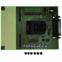
XE8000EV108
Description
EVAL BOARD FOR XE8806/XE8807
Manufacturer
Semtech
Type
MCUr
Specifications of XE8000EV108
Contents
Fully Assembled Evaluation Board
For Use With/related Products
XE88LC06AMI026
Lead Free Status / RoHS Status
Contains lead / RoHS non-compliant


17.9 Counter / Timer mode
The counters in counter / timer mode are generally used to generate interrupts after a predefined number of clock
periods applied on the counter clock input.
Each counter can be set individually either in upcount mode by setting CntXDownUp in the register
RegCntConfig1 or in downcount mode by resetting this bit. Counters A and B can be cascaded to behave as a 16
bit counter by setting CascadeAB in the RegCntConfig1 register. Counters C and D can be cascaded by setting
CascadeCD. When cascaded, the up/down count modes of the counters B and D are defined respectively by the
up/down count modes set for the counters A and C.
When in upcount mode, the counter will start incrementing from zero up to the target value which has been written
in the corresponding RegCntX register(s). When the counter content is equal to the target value, an interrupt is
generated at the next counter clock pulse and the counter is loaded again with the zero value (Figure 17-2).
When in downcount mode, the counter will start decrementing from the initial load value which has been written in
the corresponding RegCntX register(s) down to the zero value. Once the counter content is equal to zero, an
interrupt is generated at the next counter clock pulse and the counter is loaded again with the load value (Figure
17-2).
Be careful to select the counter mode (no capture, not PWM, specify cascaded or not and up or down counting
mode) before writing any target or load value to the RegCntX register(s). This ensures that the counter will start
from the correct initial value. When counters are cascaded, both counter registers must be written to ensure that
both cascaded counters will start from the correct initial values.
The stopping and consecutive starting of a counter in counter mode without a target or load value write operation in
between can generate an interrupt if this counter has been stopped at the zero value (downcount) or at it’s target
value (upcount). This interrupt is additional to the interrupt which has already been generated when the counter
reached the zero or the target value.
© Semtech 2006
CascadeCD
0
1
0
1
CountPWM1
Table 17-13: Operating modes of the counters C and D
0
0
1
1
Counter 8b
Downup: C
Downup: C
Counter C
PWM 8b
mode
PWM 10 – 16b CD
Counter 16b CD
Downup: C
Downup: C
17-7
Counter 8b
Downup: D
Counter 8b
Downup: D
Counter D
mode
Counter
Counter
source
IrqC
CD
C
-
-
XE8806A/XE8807A
Counter
Counter
source
IrqD
D
D
-
-
PWM CD
function
PWM C
PB(1)
PB(1)
PB(1)
www.semtech.com
Related parts for XE8000EV108
Image
Part Number
Description
Manufacturer
Datasheet
Request
R

Part Number:
Description:
EVALUATION BOARD
Manufacturer:
Semtech
Datasheet:
Part Number:
Description:
EVALUATION BOARD
Manufacturer:
Semtech
Datasheet:
Part Number:
Description:
VOLTAGE SUPPRESSOR, TRANSIENT SEMTECH
Manufacturer:
Semtech
Datasheet:

Part Number:
Description:
HIGH VOLTAGE CAPACITORS MONOLITHIC CERAMIC TYPE
Manufacturer:
Semtech Corporation
Datasheet:
Part Number:
Description:
EZ1084CM5.0 AMP POSITIVE VOLTAGE REGULATOR
Manufacturer:
Semtech Corporation
Datasheet:
Part Number:
Description:
3.0 AMP LOW DROPOUT POSITIVE VOLTAGE REGULATORS
Manufacturer:
Semtech Corporation
Datasheet:
Part Number:
Description:
Manufacturer:
Semtech Corporation
Datasheet:
Part Number:
Description:
RailClamp Low Capacitance TVS Diode Array
Manufacturer:
Semtech Corporation
Datasheet:
Part Number:
Description:
Manufacturer:
Semtech Corporation
Datasheet:
Part Number:
Description:
Manufacturer:
Semtech Corporation
Datasheet:
Part Number:
Description:
Manufacturer:
Semtech Corporation
Datasheet:
Part Number:
Description:
Manufacturer:
Semtech Corporation
Datasheet: