SI1140DK Silicon Laboratories Inc, SI1140DK Datasheet - Page 7
SI1140DK
Manufacturer Part Number
SI1140DK
Description
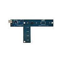
BOARD EVAL SI1143-A10-GM
Manufacturer
Silicon Laboratories Inc
Series
QuickSense™r
Specifications of SI1140DK
Sensor Type
Proximity, Infrared and Ambient Light
Interface
USB
Voltage - Supply
5V, USB
Embedded
Yes, MCU, 8-Bit
Utilized Ic / Part
C8051F800, Si1143
Data Bus Width
8 bit
Interface Type
USB
Operating Voltage
5 V
For Use With/related Products
Si1140
Lead Free Status / RoHS Status
Contains lead / RoHS non-compliant
Sensitivity
-
Sensing Range
-
Lead Free Status / RoHS Status
Contains lead / RoHS non-compliant
Other names
336-1971


Name
G10
G12
G13
G14
G15
G16
G17
G18
G19
G20
G21
G11
G0
G1
G2
G3
G4
G5
G6
G7
G8
G9
X(mm)
Y(mm)
Z(mm)
iLED1
iLED2
iLED3
PS1bl
PS2bl
PS3bl
Label
Rad1
Rad2
Rad3
VIS s
PS st
IR st
PS2
PS3
PS1
N/A
N/A
VIS
IR
Linearized Distance Measurements
Estimated Location Coordinates
LED Drive Current Levels
AutoRanging Ambient Outputs
AutoRanging PS Outputs
State of Ambient Visible System
State of Ambient IR System
State of PS System
PS Baseline Levels
Unused
Type
Table 1. Generic Data Channels
Rev. 0.2
Using characterization of the PS measurements with
objects at certain distances, it is possible to estimate the
distance of an object based on the PS measurement
value. These three channels represent the distance esti-
mations for each LED's measurement.
With the approximate distance measurements above, an
X, Y, and Z estimation can be made. These estimations
are given in units of mm.
Each LED driver has a specific LED drive current setting
for it. These values are given in units of mA.
AutoRanging will automatically change the modes of the
photodiodes to avoid saturation. When changing modes,
the raw data output changes levels, but AutoRanging will
scale the raw data so that all measurements are on the
same scale. The output from this channel is the pro-
cessed value which can be used without knowledge of
the photodiode modes.
These channels are the AutoRanging PS output from
the device. Raw data measurements are processed by
the AutoRanging firmware to make all the readings
across different modes have the same magnitude. Since
the device switches modes to compensate for ambient
light, the raw data will show jumps when changing
modes. These outputs will not display the jumps
because the firmware is stitching the raw outputs
together.
These channels help indicate what mode the sensor is in
during each of their respective measurements. The four
possible modes are as follows: Low Light, High Sensitiv-
ity, High Signal, and Sunlight. These modes are num-
bered from zero to three. For more information about
each mode, please consult the data sheet.
AutoRanging uses baselining to determine the no-detect
threshold for readings. Any readings below the values
shown on these channels will be considered no-detect
readings. Any values higher than this baseline will be
shown in the AutoRanging PS Outputs above.
The unused channels are not in use by software, but
they are available in firmware to use as needed.
Description
Si1140-DK
7
Related parts for SI1140DK
Image
Part Number
Description
Manufacturer
Datasheet
Request
R

Part Number:
Description:
SMD/C°/SINGLE-ENDED OUTPUT SILICON OSCILLATOR
Manufacturer:
Silicon Laboratories Inc
Part Number:
Description:
Manufacturer:
Silicon Laboratories Inc
Datasheet:
Part Number:
Description:
N/A N/A/SI4010 AES KEYFOB DEMO WITH LCD RX
Manufacturer:
Silicon Laboratories Inc
Datasheet:
Part Number:
Description:
N/A N/A/SI4010 SIMPLIFIED KEY FOB DEMO WITH LED RX
Manufacturer:
Silicon Laboratories Inc
Datasheet:
Part Number:
Description:
N/A/-40 TO 85 OC/EZLINK MODULE; F930/4432 HIGH BAND (REV E/B1)
Manufacturer:
Silicon Laboratories Inc
Part Number:
Description:
EZLink Module; F930/4432 Low Band (rev e/B1)
Manufacturer:
Silicon Laboratories Inc
Part Number:
Description:
I°/4460 10 DBM RADIO TEST CARD 434 MHZ
Manufacturer:
Silicon Laboratories Inc
Part Number:
Description:
I°/4461 14 DBM RADIO TEST CARD 868 MHZ
Manufacturer:
Silicon Laboratories Inc
Part Number:
Description:
I°/4463 20 DBM RFSWITCH RADIO TEST CARD 460 MHZ
Manufacturer:
Silicon Laboratories Inc
Part Number:
Description:
I°/4463 20 DBM RADIO TEST CARD 868 MHZ
Manufacturer:
Silicon Laboratories Inc
Part Number:
Description:
I°/4463 27 DBM RADIO TEST CARD 868 MHZ
Manufacturer:
Silicon Laboratories Inc
Part Number:
Description:
I°/4463 SKYWORKS 30 DBM RADIO TEST CARD 915 MHZ
Manufacturer:
Silicon Laboratories Inc
Part Number:
Description:
N/A N/A/-40 TO 85 OC/4463 RFMD 30 DBM RADIO TEST CARD 915 MHZ
Manufacturer:
Silicon Laboratories Inc
Part Number:
Description:
I°/4463 20 DBM RADIO TEST CARD 169 MHZ
Manufacturer:
Silicon Laboratories Inc