STEVAL-MKI019V1 STMicroelectronics, STEVAL-MKI019V1 Datasheet - Page 4
STEVAL-MKI019V1
Manufacturer Part Number
STEVAL-MKI019V1
Description
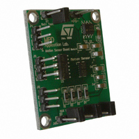
BOARD DEMO LIS302SG
Manufacturer
STMicroelectronics
Series
MEMSr
Specifications of STEVAL-MKI019V1
Design Resources
STEVAL-MKI019V1 Gerber Files STEVAL-MKI019V1 Schematic STEVAL-MKI019V1 Bill of Materials
Sensor Type
Accelerometer, 3 Axis
Sensing Range
±2g
Interface
Analog
Sensitivity
0.145 x Vdd = V/g
Voltage - Supply
3 V ~ 3.6 V
Embedded
No
Utilized Ic / Part
LIS302SG
Lead Free Status / RoHS Status
Lead free / RoHS Compliant
Other names
497-8203


Demonstration kit description
1.2
1.2.1
1.2.2
1.2.3
4/8
Driving Power-down and self-test signals
The board allows the control of the Power-down and Self-test signals through the use of test
points (marked J3 and J7, respectively) and jumpers.
Power-down
When the jumper is removed from J3 (Power-down,
normal mode, otherwise it is in power-down mode.
Self-test
When the jumper is removed from J7 (Self-Test,
disabled. In order to activate the self-test feature the jumper must be inserted into J7.
When this function is activated the seismic mass of the sensor is moved by means of an
electrostatic test-force, simulating a definite input acceleration. Under these conditions the
sensor outputs will exhibit a voltage change in their DC levels as specified in the datasheet
of the LIS302SG sensor.
Multiplexed output
The device provides an embedded multiplexer to allow the redirection of either the analog
output signals Vout
operation with a single channel A/D converter. Output selection can be achieved through
jumpers J6 and J9 (S0 and S1,
Table 1.
S1 pin
MUX I/O table
0
0
1
1
x
, Vout
y
, and Vout
Figure
z
or of an auxiliary input signal onto a single pin for
S0 pin
3, ref3). Refer to
0
1
0
1
Figure
Figure
Table 1
3, ref2) the self-test feature is
3, ref1) the MEMS sensor is in
for MUX configuration.
Vout=Aux_in
MUX status
Vout=Vout X
Vout=Vout Y
Vout=Vout Z
UM0537
Related parts for STEVAL-MKI019V1
Image
Part Number
Description
Manufacturer
Datasheet
Request
R

Part Number:
Description:
BOARD EVAL FOR MEMS SENSORS
Manufacturer:
STMicroelectronics
Datasheet:

Part Number:
Description:
EVALBOARD/STEVAL-ISV014V1
Manufacturer:
STMicroelectronics
Part Number:
Description:
BOARD EVAL FOR ST802RT1
Manufacturer:
STMicroelectronics
Datasheet:

Part Number:
Description:
BOARD EVAL FOR VACUUM CLEANER
Manufacturer:
STMicroelectronics
Datasheet:

Part Number:
Description:
KIT DEV STARTER ST10F276Z5
Manufacturer:
STMicroelectronics
Datasheet:

Part Number:
Description:
BOARD LED CTLR/DVR STLED316S
Manufacturer:
STMicroelectronics
Datasheet:

Part Number:
Description:
BOARD EVAL BLDC SENSORLESS MOTOR
Manufacturer:
STMicroelectronics
Datasheet:

Part Number:
Description:
BOARD ELECT FISCAL CASH REGISTER
Manufacturer:
STMicroelectronics
Datasheet:

Part Number:
Description:
BOARD EVAL BIPO SOLUTION FOR PFC
Manufacturer:
STMicroelectronics
Datasheet:

Part Number:
Description:
BOARD EVAL UPS 450W VOUT=220V
Manufacturer:
STMicroelectronics
Datasheet:
Part Number:
Description:
STMicroelectronics [RIPPLE-CARRY BINARY COUNTER/DIVIDERS]
Manufacturer:
STMicroelectronics
Datasheet:
Part Number:
Description:
STMicroelectronics [LIQUID-CRYSTAL DISPLAY DRIVERS]
Manufacturer:
STMicroelectronics
Datasheet:
Part Number:
Description:
BOARD EVAL FOR MEMS SENSORS
Manufacturer:
STMicroelectronics
Datasheet: