EK65 Cirrus Logic Inc, EK65 Datasheet

KIT EVALUATION FOR MP400FC

EK65

Manufacturer Part Number
EK65
Description
KIT EVALUATION FOR MP400FC
Manufacturer
Cirrus Logic Inc
Series
Apex Precision Power™r
Datasheets

Specifications of EK65

Channels Per Ic
1 - Single
Amplifier Type
Power
Output Type
Single-Ended
Board Type
Bare (Unpopulated)
Utilized Ic / Part
MP400FC
Product
Amplifier Modules
Lead Free Status / RoHS Status
Contains lead / RoHS non-compliant
Operating Temperature
-
Current - Output / Channel
-
Voltage - Supply, Single/dual (±)
-
-3db Bandwidth
-
Slew Rate
-
Current - Supply (main Ic)
-
Lead Free Status / RoHS Status
Lead free / RoHS Compliant, Contains lead / RoHS non-compliant
Other names
598-1484
Introduction
The EK65 Evaluation kit is designed to provide a convenient way to breadboard and evaluate design ideas for the
MP400FC power operational amplifier. The evaluation board is pre-wired for all required external components. The
evaluation board has been laid out and labeled to easily configure the high voltage operational amplifier in a non-
inverting differential configuration for single supply operation using the MP400FC boost supply (Refer to Application
Note 21). However, the evaluation board is flexible enough to analyze a multitude of standard or proprietary circuit
configurations.
Before You Get Started
Figure 1 - EK65 Schematic
Parts List (Included with kit)
Ref.
N/C
N/C
N/C
N/C
N/C
BJ1-6
BN1
C1
Cb1
Rtrim
EK65U
Input
Vin
Analog GND
PWR GND
www.cirrus.com
+
+
Please read this data sheet in it’s entirety before starting to construct your evaluation board.
All APEX amplifiers should be handled using proper ESD precautions.
Do not change connections while the circuit is powered.
Initially set all power supplies to the minimum operating voltage allowed in the device data sheet.
The MP400FC is a high voltage amplifier with an integrated switch mode power supply. Though the input
voltage will be 50V or less, the MP400FC can generate voltages greater then 350V. The high generated
voltage will be present on the evaluation board. Caution must be used when working with the evaluation
board.
Input
–Vs
Vin
Apex P/N
HS26
MS11
EVAL65
93505A430
90272A105
571-0100
146510CJ
ZX7R105KTL
EKMQ401VSN121MP30S Cap. 120µF, 400V
T93YA203KT20
Ro1
Rin+
Ro2
Rf+
J2
Ro3
EK65 MP400
P r o d u c t I n n o v a t i o n F r o m
Rin–
Ro4
Evaluation Kit for MP400FC
Cc+
Rb1
Description/Vendor
Heat Sink
Strip of 30 cage jacks
PC board
Hex standoff, 4-40x1/4
Screw, 4-40x3/16
Banana Jack, PC
BNC, PC mount
Cap. 1 µF, 500V
Novacap
ST2225B105K501LLXW
Trim Pot, 20K
Cc–
Rtrim
20K
+
Cin
100µF
Rb2
Rset
Copyright © Cirrus Logic, Inc. 2008
CC–
–Vs
–IN
+IN
CR–
CR+
CC+
AGND
Rset
PGND
PGND
PGND
PGND
PGND
PGND
PGND
PGND
Vin
Vbias
Vin
Vin
Vin
Rf–
(All Rights Reserved)
X1
VBoost
Q2D
Q2D
Q2D
Q2D
ILIM
LFin
+Vs
Out
Qty.
J1
1
2
1
4
4
6
1
1
1
1
Rcl
Rs
20
Cs
1.5nF
+
Cb1
+
L1
+
Cb2
+
Cb3
+
Out
Cb4
Analog GND
Load
C1
1µF
APEX - EK65UREVB
EK65
AUG 2009
EK65
1

Related parts for EK65

EK65 Summary of contents

Page 1

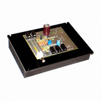
... Evaluation Kit for MP400FC Introduction The EK65 Evaluation kit is designed to provide a convenient way to breadboard and evaluate design ideas for the MP400FC power operational amplifier. The evaluation board is pre-wired for all required external components. The evaluation board has been laid out and labeled to easily configure the high voltage operational amplifier in a non- inverting differential configuration for single supply operation using the MP400FC boost supply (Refer to Application Note 21) ...

Page 2

... During assembly, refer to Figure 1, Figure 2 and the MP400FC data sheet. 1. Note that the silk screen side of the circuit board is labeled as the “component side”. The other side of the circuit board will be referred to in these instructions as the “DUT side” of the board EK65U ...

Page 3

... Out AGND Cb1 Cb2 AGND Rf- Vboost Rb1 Rtrim Rset 42 Rf+ AGND Rin+ Rin- Rb2 IC1 AGND PGND J2 Input BOTTOM VIEW Figure 2 - EVAL65 PCB Layout EK65 Cb3 Cb4 Cin Vin Do not connect AGND & PGND. See datasheet EVAL65 REV 1 Component Side 3 ...

Page 4

... PCB to the hex spacers. Use the supplied 4-40 x 3/16” screws to attach the PCB assembly to the hex spacers. 18. Hook up power and signals as necessary. The amplifier is now ready for testing. Figure 3 - EK65 Assembly EK65U ...

Related keywords