EK14 Cirrus Logic Inc, EK14 Datasheet

EVALUATION KIT FOR SIP03

EK14

Manufacturer Part Number
EK14
Description
EVALUATION KIT FOR SIP03
Manufacturer
Cirrus Logic Inc
Series
Apex Precision Power™r
Datasheets

Specifications of EK14

Channels Per Ic
1 - Single
Amplifier Type
Power
Output Type
Single-Ended
Board Type
Bare (Unpopulated)
Utilized Ic / Part
PA13, PA16
Product
Amplifier Modules
Description/function
Audio Amplifiers
Lead Free Status / RoHS Status
Contains lead / RoHS non-compliant
Operating Temperature
-
Current - Output / Channel
-
Voltage - Supply, Single/dual (±)
-
-3db Bandwidth
-
Slew Rate
-
Current - Supply (main Ic)
-
Lead Free Status / RoHS Status
Lead free / RoHS Compliant, Contains lead / RoHS non-compliant

Available stocks

Company
Part Number
Manufacturer
Quantity
Price
Part Number:
EK14
Manufacturer:
VISHAY/威世
Quantity:
20 000
INTRODUCTION
board circuits using Apex Precision Power power op amps pack-
aged in the 12-pin SIP03 package. The amplifier may be mounted
vertically with the HS20 heat sink, or horizontally. Connections
are provided for required power supply bypassing, external
compensation components, as well as current limit resistors.
A large area for component mounting provides flexibility and
makes a multitude of circuit configurations possible.
PARTS LIST
Part #
HS20
EVAL16
MS06
OX7R105KWN
CSR10
TWO7
BEFORE YOU GET STARTED
• All Apex Precision Power amplifiers should be handled using
• Always use the heat sink and thermal washers included in
• Always use adequate power supply bypassing.
• Do not change connections while the circuit is powered.
• Initially set all power supplies to the minimum operating levels
• Check for oscillations.
EK14U
The EK14 evaluation kit provides a convenient way to bread-
CAUTION
proper ESD precautions.
this kit.
allowed in the device data sheet.
www.cirrus.com
Evaluation Kit for DP Package Op Amps
Use the supplied thermal washers or ther-
mal grease between the power amplifier
and the heat sink.
EK14 PA13, PA16
P r o d u c t T e c h n o l o g y F r o m
P r o d u c t I n n o v a t i o n F r o m
Description
Heatsink
PC Board
Mating Socket
1µF Ceramic Capacitor
.15
Thermal Washer
Ω
Resistor
Copyright © Cirrus Logic, Inc. 2010
1 package
Quantity
1
1
1
2
2
(All Rights Reserved)
ASSEMBLY
1. On the silk screen side of the evaluation board, insert and
2. Solder components for your circuit. Be sure to include proper
3. Place the TW07 thermal washer on the heat sink over the
4. Mount the DUT to the HS20 by sliding under the head of the
5. Install leads of the DUT into the MS06 on the evaluation board.
solder the MS06 mating socket in DUT holes 1 – 12. Be sure
each one is fully seated.
bypassing, required compensation components and current
limit resistors. See the op amp data sheet for help in select-
ing these components. 1uF capacitors and a .15 Ω resistor
have been included with the EK12 kit but may be replaced
with other components as necessary.
mounting hole for the DUT. Place a #6 screw through the
mounting hole and thread a #6 nut onto the screw at the
back of the heat sink. Do not tighten. Note that there are
two sets of mounting holes on the HS20. Holes on one edge
allow room between the DUT and evaluation board for the
MS06 socket. The holes on the other edge are for direct
through hole mounting of the DUT to the evaluation board.
It is recommended that you use the MS06.
#6 screw and on top of the thermal washer. Tighten the nut
to the specified 8 to 10 in-lbs. (.9 to .13 N*M). Do not over
torque.
Use #6 self-tapping screws to secure the evaluation board
to the HS20 heat sink as shown in the assembly diagram
(Figure 1).
APEX − EK14UREVD
EK14
NOV 2010
EK14
1

Related parts for EK14

EK14 Summary of contents

Page 1

... Evaluation Kit for DP Package Op Amps INTRODUCTION The EK14 evaluation kit provides a convenient way to bread- board circuits using Apex Precision Power power op amps pack- aged in the 12-pin SIP03 package. The amplifier may be mounted vertically with the HS20 heat sink, or horizontally. Connections are provided for required power supply bypassing, external compensation components, as well as current limit resistors ...

Page 2

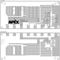
... EK14 FIGURE 1. PCB TOP SIDE SPARE SPARE BOTTOM SIDE EVAL16 R-A COMPONENT SIDE Y GND -IN +IN 6.43 DUT 1 12 -Vs GND + RLIM GND + + C4 C3 RLIM +Vs -Vs OUTPUT 3. EK14U ...

Page 3

... MERCHANTABILITY AND FITNESS FOR PARTICULAR PURPOSE, WITH REGARD TO ANY CIRRUS PRODUCT THAT IS USED IN SUCH A MANNER. IF THE CUSTOMER OR CUSTOMER’S CUSTOMER USES OR PERMITS THE USE OF CIRRUS PRODUCTS IN CRITICAL APPLICATIONS, CUSTOMER AGREES, BY SUCH USE, TO FULLY INDEMNIFY CIRRUS, ITS OFFICERS, DIRECTORS, EMPLOYEES, DISTRIBUTORS AND OTHER AGENTS FROM ANY AND ALL LIABILITY, INCLUDING ATTORNEYS’ FEES AND COSTS, THAT MAY RESULT FROM OR ARISE IN CONNECTION WITH THESE USES. Cirrus Logic, Cirrus, and the Cirrus Logic logo designs, Apex Precision Power, Apex and the Apex Precision Power logo designs are trademarks of Cirrus Logic, Inc. All other brand and product names in this document may be trademarks or service marks of their respective owners. EK14U EK14 3 ...

Related keywords