STEVAL-ILL008V1 STMicroelectronics, STEVAL-ILL008V1 Datasheet
STEVAL-ILL008V1
Specifications of STEVAL-ILL008V1


Related parts for STEVAL-ILL008V1


STEVAL-ILL008V1 Summary of contents
Page 1
HIGH EFFICIENCY SYNCRONOUS STEP UP CONVERTER 1 Features ■ 0.6 TO 5.5V OPERATING INPUT VOLTAGE ■ 1V START UP INPUT VOLTAGE ■ INTERNAL SYNCHRONOUS RECTIFIER ■ ZERO SHUT DOWN CURRENT 3.3V AND 5V FIXED OR ADJUSTABLE ■ OUTPUT VOLTAGE ...
Page 2
L6920 Table 1. Pin Description Pin Name 1 FB Output voltage selector. Connect FB to GND for Vout= OUT for Vout=3.3V. Connect external resistor divider for adjustable output voltage (from 2V to 5.2V) [see R4 ...
Page 3
Table 4. Electrical Characteristcs ( GND -40°C to 85°C and T in amb Symbol Parameter V SECTION CC V Minimum operating Input Voltage in V Minimum Start Up Input Voltage in I Quiescent Current ...
Page 4
L6920 Figure 3. Efficiency vs. Output Current 100 0.01 0.1 1 LOAD CURRENT [mA] Figure 4. Efficiency vs. Output Current 100 90 80 Vin = 1. Vout ...
Page 5
Detailed Description The L6920 is a high efficiency, low voltage step-up DC/DC converter particularly suitable for cells (Li-Ion/ polymer, NiMH respectively) battery up conversion. These performances are achieved via a strong reduction of quiescent current (10µA ...
Page 6
L6920 Figure 7. PFM mode Condition: V Trace1: Vout (50mV~/div) Trace 4: IL (100mA/div) Time div.: 5µs/div Figure 8. Heavier load - Train pulses overlapping. Trace1: V (100mV~/div) Trace 4: I out Time div.: 10 µs/div When Iload is heavier, ...
Page 7
Figure 11. No regulation. I load Trace1: V (100mV~/div) Trace 4: I out Time div.: 5 µs/div 4.1 Start-up One of the key features of L6920 is the startup at sup- ply voltage down to 1V (please see the diagram ...
Page 8
L6920 Figure 12. Demoboard Circuit +VBATT R1 N.C. LBI 2 R2 N.C. VREF 4 C4 100nF GND 6 not mounted components Table 6. Jumper J1 J2 R4, R5 should be selected in the range of 100kΩ - 10MΩ to minimize ...
Page 9
Table 7. Capacitors distributors main list Manufacturer AVX TPS KEMET T510/T494/ T495 PANASONIC EEFCD SANYO POSCAP TPA/B/C SPRAGUE 595D 5.3 Inductor selection Usually, inductors ranging between 5µH to 40µH satisfy most of the applications. Small value inductors have smaller physical ...
Page 10
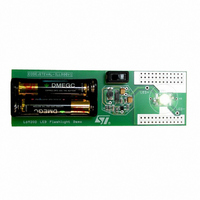
L6920 Figure 13. Demoboard Components (Top side). Figure 14. Demoboard Layout (Top side). Figure 15. Demoboard Layout (Bottom side). 10/13 4.5cm 4cm 4.5cm 4cm 4.5cm 4cm ...
Page 11
Package Information Figure 16. TSSOP8 Mechanical Data & Package Dimensions mm DIM. MIN. TYP. MAX. A 1.20 A1 0.050 0.150 A2 0.800 1.000 1.050 b 0.190 0.300 c 0.090 0.200 D (1) 2.900 3.000 3.100 E 6.200 6.400 6.650 ...
Page 12
L6920 7 Revision History Table 9. Revision History Date Revision May 2003 February 2005 12/13 1 First Issue. 2 Modified the max. value of the I Description of Changes parameter in the Table 4 pag ...
Page 13
... No license is granted by implication or otherwise under any patent or patent rights of STMicroelectronics. Specifications mentioned in this publication are subject to change without notice. This publication supersedes and replaces all information previously supplied. STMicroelectronics products are not authorized for use as critical components in life support devices or systems without express written approval of STMicroelectronics ...