STEVAL-ISA023V2 STMicroelectronics, STEVAL-ISA023V2 Datasheet - Page 25
STEVAL-ISA023V2
Manufacturer Part Number
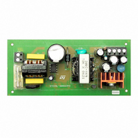
STEVAL-ISA023V2
Description
EVAL BOARD 24W NEG OUT VIPER53E
Manufacturer
STMicroelectronics
Series
VIPER™r
Type
AC/DC Switching Convertersr
Specifications of STEVAL-ISA023V2
Mfg Application Notes
VIPer53EDIP - AppNote
Design Resources
STEVAL-ISA023V2 Gerber Files STEVAL-ISA023V2 Schematic STEVAL-ISA023V2 Bill of Materials
Main Purpose
AC/DC, Primary Side
Outputs And Type
2, Isolated
Power - Output
24W
Voltage - Output
-5V, -12V
Current - Output
3A, 800mA
Voltage - Input
90 ~ 265VAC
Regulator Topology
Flyback
Frequency - Switching
60kHz
Board Type
Fully Populated
Utilized Ic / Part
VIPer53
Input Voltage
90 V to 265 V
Output Voltage
- 5 V, - 12 V
Product
Power Management Modules
Silicon Manufacturer
ST Micro
Silicon Core Number
VIPer53-E
Kit Application Type
Power Management
Application Sub Type
SMPS
Kit Contents
Board
Lead Free Status / RoHS Status
Lead free / RoHS Compliant
For Use With/related Products
VIPer53-E
Other names
497-5866
Available stocks
Company
Part Number
Manufacturer
Quantity
Price
Company:

Part Number:
STEVAL-ISA023V2
Manufacturer:
STMicroelectronics
Quantity:
1


VIPer53 - E
11
Transconductance error amplifier
The VIPer53-E includes a transconductance error amplifier. Transconductance Gm is the
change in output current I
Equation 8
The output impedance Z
Equation 9
This last equation shows that the open loop gain A
Equation 10
where Gm value for VIPer53 is typically 1.4mA/V.
Gm is well defined by specification, but Z
tolerances. An impedance Z must be connected between the COMP pin and ground in order
to accurately define the transfer function F of the error amplifier, the following equation, very
similar to the one above:
Equation 11
The error amplifier frequency response is shown in .0 for different values of a simple
resistance connected on the COMP pin. The unloaded transconductance error amplifier
shows an internal Z
the COMP pin to achieve different compensation methods. A capacitor provides an
integrator function, thus eliminating the DC static error, and a resistance in series leads to a
flat gain at higher frequency, introducing a zero level and ensuring a correct phase margin.
This configuration illustrated in
the error amplifier transfer function for a typical set of values of C
Note that a 10nF capacitor (8nF, minimum value) should always be connected to the COMP
pin to ensure a correct stability of the internal error amplifier.
The complete converter open loop transfer function can be built from both power cell and
error amplifier transfer functions. A theoretical example can be seen in
discontinuous mode flyback loaded by a simple resistor, regulated from primary side (no
COMP
COMP
COMP
of about 140K . More complex impedances can be connected on
Z
COMP
at the output of this amplifier (COMP pin) can be defined as:
Figure
versus change in input voltage V
A
=
VOL
F s
22, for the schematic and
--------------------- -
Gm
V
I
COMP
COMP,
COMP
=
=
=
Gm
Gm
------------------- -
=
I
COMP
and therefore A
V
--------- -
Gm
DD
Z
1
Z s
VOL
COMP
--------------------- -
can be related to Gm and Z
Transconductance error amplifier
V
V
COMP
DD
VOL,
Figure 23 on page 28
DD
COMP
. Thus:
are subject to large
and R
Figure 24
COMP
for a
.
COMP
for
25/36
:
Related parts for STEVAL-ISA023V2
Image
Part Number
Description
Manufacturer
Datasheet
Request
R

Part Number:
Description:
BOARD RGB CTR ST7,STP08C596MTR
Manufacturer:
STMicroelectronics
Datasheet:

Part Number:
Description:
Power Management IC Development Tools Full Speed USB to RS232 Bridge Demo
Manufacturer:
STMicroelectronics
Datasheet:
Part Number:
Description:
Power Management IC Development Tools 2.5W solar eval BRD USB SPV1040 LD39050
Manufacturer:
STMicroelectronics
Datasheet:

Part Number:
Description:
BOARD EVAL FOR MEMS SENSORS
Manufacturer:
STMicroelectronics
Datasheet:

Part Number:
Description:
KIT DEV STARTER ST10F276Z5
Manufacturer:
STMicroelectronics
Datasheet:

Part Number:
Description:
BOARD EVAL HDMI $ VIDEO SWITCH
Manufacturer:
STMicroelectronics
Datasheet:

Part Number:
Description:
BOARD DEMO ACCELEROMETER DIL24
Manufacturer:
STMicroelectronics
Datasheet:

Part Number:
Description:
BOARD STLM75/STDS75/ST72F651
Manufacturer:
STMicroelectronics
Datasheet:

Part Number:
Description:
EVAL BOARD 3AXIS MEMS ACCELLRMTR
Manufacturer:
STMicroelectronics
Datasheet:

Part Number:
Description:
BOARD EVAL 8BIT MICRO + TDE1708
Manufacturer:
STMicroelectronics
Datasheet:
Part Number:
Description:
STMicroelectronics [RIPPLE-CARRY BINARY COUNTER/DIVIDERS]
Manufacturer:
STMicroelectronics
Datasheet:
Part Number:
Description:
STMicroelectronics [LIQUID-CRYSTAL DISPLAY DRIVERS]
Manufacturer:
STMicroelectronics
Datasheet:
Part Number:
Description:
BOARD EVAL FOR MEMS SENSORS
Manufacturer:
STMicroelectronics
Datasheet: