NCP1207AADAPGEVB ON Semiconductor, NCP1207AADAPGEVB Datasheet

EVAL BOARD FOR NCP1207AADAPG

NCP1207AADAPGEVB

Manufacturer Part Number
NCP1207AADAPGEVB
Description
EVAL BOARD FOR NCP1207AADAPG
Manufacturer
ON Semiconductor

Specifications of NCP1207AADAPGEVB

Design Resources
NCP1207AADAPGEVB BOM NCP1207AADAPGEVB Gerber Files NCP1207A EVB Schematic
Main Purpose
AC/DC, Primary Side
Outputs And Type
1, Isolated
Power - Output
24W
Voltage - Output
12V
Current - Output
2A
Voltage - Input
180 ~ 240VAC
Regulator Topology
Flyback
Frequency - Switching
70kHz
Board Type
Fully Populated
Utilized Ic / Part
NCP1207
Lead Free Status / RoHS Status
Lead free / RoHS Compliant
For Use With/related Products
NCP1207AADAPG
Other names
NCP1207AADAPGEVBOS
AND8127/D
Implementing NCP1207 in
QR 24 W AC−DC Converter
with Synchronous Rectifier
Prepared by: Petr Lidak
ON Semiconductor
Introduction
current−mode free running quasi−resonant Flyback offline
converter.
notebooks, offline battery chargers, consumer electronics
(DVD players, set−top boxes, TVs), etc.
efficiency improvement, and maximum safety has been
taken into account while designing the NCP1207.
supply that can meet all those requirements. This can be
achieved with help of the following NCP1207 main
features:
June, 2004 − Rev. 1
The NCP1207 is a controller dedicated for driving the
This converter is designed for consumer products like
The growing interest for EMI pollution reduction,
By implementing the NCP1207 one can build a power
Current−Mode Control: Cycle−by−cycle primary
current observation is helping to prevent any significant
primary overcurrent which would cause transformer’s
core saturation and consequent serious power supply
failure.
Critical Mode Quasi−resonant Operation: Prevents the
converter operation in Continuous Conduction Mode in
any input and output condition. It is provided by the
zero crossing detection of the auxiliary winding’s
voltage.
By addition of the reasonable delay the switch turn−on
instant can be shifted to the minimum (valley) of drain
voltage. This improves EMI noise and efficiency.
Dynamic Self−Supply: Ensures IC proper operation in
applications where the output voltage varies during
operation like battery chargers. The DSS also supplies
the IC when the overvoltage event is being latched and
converter operation is stopped.
Overvoltage Protection: By sampling the plateau
voltage on the auxiliary winding, the NCP1207 enters
into latched fault condition whenever the overvoltage is
detected. The controller stays fully latched until the
V
the power supply from the mains outlet and re−plugs it.
The OVP threshold can be adjusted externally.
Semiconductor Components Industries, LLC, 2004
CC
decreases below 4.0 V, e.g. when the user unplugs
1
The 24 W AC−DC Adaptor Board Specification
ratings.
Figure 1.
Transformer Design
The requested output power is 24 W.
voltage is:
Output Power
Output Voltage
Output Current
Minimum Input Voltage
Maximum Input Voltage
Maximum Switching Frequency
V bulk− min + V AC− min 2 + 180 @ 2 + 255 VDC
V bulk− max + V AC− max 2 + 240 @ 2 + 339 VDC
P IN +
I IN−AVG +
The adaptor has following maximum and performance
The schematic diagram of the adaptor can be seen in
The bulk capacitor voltage than can be calculated:
Assuming 87% efficiency the input power is equal to:
The average value of input current at minimum input
Over−Load Protection: by continuously monitoring the
feedback loop activity, NCP1207 enters hiccup
operation as soon as the power supply is overloaded. As
soon as overload condition disappears, the NCP
resumes operation.
P OUT
h
V bulk− min
+
P IN
0.87
24
APPLICATION NOTE
+ 27.6 W
http://onsemi.com
+
27.6
255
+ 108 mA
Publication Order Number:
180 VAC
240 VAC
12 VDC
70 kHz
AND8127/D
24 W
2.0 A
(eq. 1)
(eq. 2)
(eq. 3)
(eq. 4)

Related parts for NCP1207AADAPGEVB

NCP1207AADAPGEVB Summary of contents

Page 1

... AND8127/D Implementing NCP1207 AC−DC Converter with Synchronous Rectifier Prepared by: Petr Lidak ON Semiconductor Introduction The NCP1207 is a controller dedicated for driving the current−mode free running quasi−resonant Flyback offline converter. This converter is designed for consumer products like notebooks, offline battery chargers, consumer electronics (DVD players, set− ...

Page 2

Taking into account the absence of a clamping network the suitable reflected primary winding voltage for 800 V rated MOSFET switch is: V flbk + 800 bulk− max * V spike + 800 * 339 * 330 ...

Page 3

Since skin effect and eddy currents play a significant role in the Flyback topology at given switching frequency the Litz wire is used. It consists of 4 wires each with diameter 0.12 mm. To reduce the leakage inductance the primary ...

Page 4

With regard to TL431 input leakage current, the resistor divider’s current of 500 mA was selected. The resistor R12 then can be calculated as follows: V TL431 2 4.7 kW 500 @ ...

Page 5

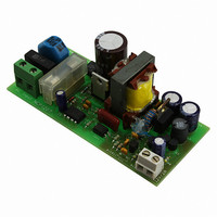
PCB Layout Proper printed circuit board layout is essential for good operation of the whole converter. It also influences the EMI signature in both conducted and radiated measurements important to ensure good grounding technique and keep all high ...

Page 6

Practical Results One of the most important parameters considered during the converter design is the overall power conversion efficiency. For this reason the synchronized output rectifier was utilized. Table 1 lists the measured results for converter working at minimum specified ...

Page 7

The following pictures of the basic voltage waveforms demonstrate the operation of the converter at specific conditions. Figure 6 shows in top trace the gate driver voltage and in bottom trace primary switch’s drain voltage at full load. Figure 6. ...

Page 8

... Figure 11. Detailed View of the Burst Pulse N. American Technical Support: 800−282−9855 Toll Free USA/Canada Japan: ON Semiconductor, Japan Customer Focus Center 2−9−1 Kamimeguro, Meguro−ku, Tokyo, Japan 153−0051 Phone: 81−3−5773−3850 http://onsemi.com 8 ON Semiconductor Website: http://onsemi ...

Related keywords