STEVAL-ISA054V1 STMicroelectronics, STEVAL-ISA054V1 Datasheet
STEVAL-ISA054V1
Specifications of STEVAL-ISA054V1
Available stocks


Related parts for STEVAL-ISA054V1


STEVAL-ISA054V1 Summary of contents
Page 1
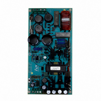
... W in total. The 5/3.3 V output is obtained by means of an integrated DC-DC converter based on L5970D, connected to the 24 V output, and adjustable by means of an external voltage divider. The board is orderable with the order code "STEVAL-ISA054V1". Figure 1. STEVAL-ISA054V1 board layout: components Figure 2 ...
Page 2
Contents Contents 1 Demonstration board description . . . . . . . . . . . . . . . . . . . . . . . . . . . . . . 5 2 Specifics of ...
Page 3
... Main specifications . . . . . . . . . . . . . . . . . . . . . . . . . . . . . . . . . . . . . . . . . . . . . . . . . . . . . . . . 5 Table 2. Absolute maximum ratings . . . . . . . . . . . . . . . . . . . . . . . . . . . . . . . . . . . . . . . . . . . . . . . . . . 9 Table 3. Electrical characteristics: on /off states Table 4. Electrical characteristics: dynamic . . . . . . . . . . . . . . . . . . . . . . . . . . . . . . . . . . . . . . . . . . . 10 Table 5. Switching times . . . . . . . . . . . . . . . . . . . . . . . . . . . . . . . . . . . . . . . . . . . . . . . . . . . . . . . . . . 10 Table 6. Output voltage . . . . . . . . . . . . . . . . . . . . . . . . . . . . . . . . . . . . . . . . . . . . . . . . . . . . . . . . . . 14 Table 7. STEVAL-ISA054V1: bill of materials Table 8. 1500 V power MOSFET product range . . . . . . . . . . . . . . . . . . . . . . . . . . . . . . . . . . . . . . . 21 Table 9. Document revision history . . . . . . . . . . . . . . . . . . . . . . . . . . . . . . . . . . . . . . . . . . . . . . . . . 22 Doc ID 15343 Rev 1 List of tables 3/23 ...
Page 4
... List of figures List of figures Figure 1. STEVAL-ISA054V1 board layout: components . . . . . . . . . . . . . . . . . . . . . . . . . . . . . . . . . . 1 Figure 2. STEVAL-ISA054V1 board layout: board layout and tracks . . . . . . . . . . . . . . . . . . . . . . . . . 1 Figure 3. Circuit schematic . . . . . . . . . . . . . . . . . . . . . . . . . . . . . . . . . . . . . . . . . . . . . . . . . . . . . . . . . 7 Figure 4. Mechanical layout . . . . . . . . . . . . . . . . . . . . . . . . . . . . . . . . . . . . . . . . . . . . . . . . . . . . . . . . 11 Figure 5. Electrical schematic . . . . . . . . . . . . . . . . . . . . . . . . . . . . . . . . . . . . . . . . . . . . . . . . . . . . . . 11 Figure 6. DC-DC converter . . . . . . . . . . . . . . . . . . . . . . . . . . . . . . . . . . . . . . . . . . . . . . . . . . . . . . . . 13 Figure 7. Drain voltage (blue) and current (green) at 230 Vac, full load . . . . . . . . . . . . . . . . . . . . . . 14 Figure 8. ...
Page 5
... Demonstration board description The proposed board is based on a flyback converter and employs as primary switch the STW9N150, a 2.5 Ω 1500 V power MOSFET, which uses STMicroelectronics proprietary high voltage "mesh overlay" technology. Thanks to this technology, the switch features very low R device is available in a TO-247 package. ...
Page 6
Demonstration board description The flyback transformer is manufactured by Magnetica, and guarantees that the safety insulation is in accordance with the EN60950 low-voltage directive. Transformer specifications are detailed in 6/23 Chapter 3. Doc ID 15343 Rev 1 UM0674 ...
Page 7
UM0674 Figure 3. Circuit schematic Doc ID 15343 Rev 1 Demonstration board description VCC GND 7 5 AM01983v1 7/23 ...
Page 8
Demonstration board description The 5 V output is obtained from the 24 V output by means of an integrated power IC, the L5970D. The L5970D is a step-down monolithic power switching regulator with a switch current limit ...
Page 9
... UM0674 2 Specifics of the STW9N150 MOSFET Using the well-consolidated high voltage MESH OVERLAY™ process, STMicroelectronics has designed an advanced family of power MOSFETs with outstanding performances. The strengthened layout coupled with the company's proprietary-edge termination structure gives the lowest R In particular, the proposed board employs as primary switch the STW9N150, a 1.8 Ω 1500 V power MOSFET ...
Page 10
Specifics of the STW9N150 MOSFET Table 4. Electrical characteristics: dynamic Symbol (1) g Forward transconductance fs Input capacitance Ciss Output capacitance Coss Reverse transfer Crss capacitance Equivalent output C eq. oss capacitance R Gate input resistance g Q Total gate ...
Page 11
UM0674 3 Flyback transformer Figure 4 and Figure 5 Section 3.1 lists the technical specifications for the transformer. Figure 4. Mechanical layout Figure 5. Electrical schematic show the electrical and mechanical specifications of the transformer. Doc ID 15343 Rev 1 ...
Page 12
Flyback transformer 3.1 Transformer specifications ● Inductance: (at 1 kHz, 20 deg C) – Primary (pin 2-5): 2.25 mH +/-15 % – Auxiliary (pin 6-7): 3.3 µH +/-15 % – Secondary (pin 13,12-9,10): 9 µH +/-15 % ● Resistance: (at ...
Page 13
UM0674 4 DC-DC converter Figure 6 shows the schematic of the converter. The device uses an internal P-channel DMOS transistor, with a typical R a bootstrap capacitor, and guarantees high efficiency. An internal oscillator fixes the switching frequency at 250 ...
Page 14
Primary and output waveforms 5 Primary and output waveforms 5.1 Primary side waveforms All measurements have been performed at ambient temperature (about 25°C), with the input voltage in the range of 180 Vac normal operation at no load and full ...
Page 15
UM0674 Figure 8. DC bus voltage at 180-265 Vac output current 5.2 Output side waveforms Figure below shows the output voltage ripple for output at full load. The output voltage ripple has been minimized by choosing output ...
Page 16
Primary and output waveforms Figure 10 shows the 24 V output voltage time response at start-up. Figure 10 output voltage at start-up Figure 11 shows the output voltage and current for diode STPS20120CFP. The green waveform is the ...
Page 17
UM0674 6 System time response at load variations Some tests have been done varying the load current, switching between the maximum and minimum values and vice versa. switching from 0.4 A, with a response time of 30 ...
Page 18
Efficiency 7 Efficiency Figure 14 shows the ratio pout/pin as a function of the input AC voltage. The input voltage range is between 180 V and 265 Vrms. The output load current is fixed for 24 Vdc ...
Page 19
... UM0674 8 Bill of material Table 7. STEVAL-ISA054V1: bill of materials Reference Cin Cout Co1,Co2,Co3,Co4,C16 C10 C12,C13 C14 C15 D2 D3,D5 D6,D9,D10,D11 L2,L3, Part / value 10 µ ceramic 470 µF, 10 V-ZL series 560 µF, 35 V-ZL series 68 µF, 450 V-MXC series 330 µ 2.2 nF, 1600 V R73 KP series 68 µF, 450 V-MXC series ...
Page 20
... Bill of material Table 7. STEVAL-ISA054V1: bill of materials Reference Q6 Q7 RT1 R1, R17 R2,R4,R7, R19 R10 R12 R11 R13 R14 R15 R16 R18 R20 R23 R26 R27 R28 R29 SW1 20/23 Part / value 2SD882 2SB772 NTC - 10 330 kΩ MΩ, 1 kΩ, 1% 2.2 kΩ kΩ ...
Page 21
UM0674 9 Conclusion This document introduces a complete solution for an auxiliary power supply in a typical industrial application. The board has been fully characterized, showing good performance in all test conditions, confirming the suitability of the proposed solution for ...
Page 22
Revision history 10 Revision history Table 9. Document revision history Date 24-Sep-2009 22/23 Revision 1 Initial release. Doc ID 15343 Rev 1 UM0674 Changes ...
Page 23
... UM0674 Information in this document is provided solely in connection with ST products. STMicroelectronics NV and its subsidiaries (“ST”) reserve the right to make changes, corrections, modifications or improvements, to this document, and the products and services described herein at any time, without notice. All ST products are sold pursuant to ST’s terms and conditions of sale. ...