STEVAL-ISA029V1 STMicroelectronics, STEVAL-ISA029V1 Datasheet - Page 19
STEVAL-ISA029V1
Manufacturer Part Number
STEVAL-ISA029V1
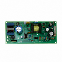
Description
BOARD EVAL BASED ON VIPER53-E
Manufacturer
STMicroelectronics
Series
VIPER™r
Type
MOSFET & Power Driverr
Specifications of STEVAL-ISA029V1
Design Resources
STEVAL-ISA029V1 Gerber Files STEVAL-ISA029V1 Schematic STEVAL-ISA029V1 Bill of Material
Main Purpose
AC/DC, Primary Side
Outputs And Type
3, Isolated
Power - Output
13W
Voltage - Output
12V, 3.3V, -24V
Current - Output
1A, 100mA, 40mA
Voltage - Input
85 ~ 300VAC
Regulator Topology
Flyback
Frequency - Switching
60kHz
Board Type
Fully Populated
Utilized Ic / Part
VIPer53
Input Voltage
85 V to 300 V
Output Voltage
12 V
Product
Power Management Modules
Silicon Manufacturer
ST Micro
Silicon Core Number
VIPer53-E
Kit Application Type
Power Management
Application Sub Type
Power Supply
Kit Contents
Board
Rohs Compliant
No
Lead Free Status / RoHS Status
Lead free / RoHS Compliant
For Use With/related Products
VIPer53-E
Other names
497-6458
STEVAL-ISA029V1
STEVAL-ISA029V1


VIPer53 - E
7
Current mode topology
The VIPer53-E implements the conventional current mode control method for regulating the
output voltage. This kind of feedback includes two nested regulation loops:
The inner loop controls the peak primary current cycle by cycle. When the Power MOSFET
output transistor is on, the inductor current (primary side of the transformer) is monitored
with a SenseFET technique and converted into a voltage. When V
power switch is turned off. This structure is completely integrated as shown on the Block
Diagram
function and the PWM latch. The following formula gives the peak current in the Power
MOSFET according to the compensation voltage:
Equation 1
The outer loop defines the level at which the inner loop regulates peak current in the power
switch. For this purpose, V
optocoupler in secondary feedback configuration, see
accordingly the peak drain current for each switching cycle.
As the inner loop regulates the peak primary current in the primary side of the transformer,
all input voltage changes are compensated for before impacting the output voltage. This
results in an improved line regulation, instantaneous correction to line changes, and better
stability for the voltage regulation loop.
Current mode topology also provides a good converter start-up control. The compensation
voltage can be controlled to increase slowly during the start-up phase, so the peak primary
current will follow this soft voltage slope to provide a smooth output voltage rise, without any
overshoot. The simpler voltage mode structure which only controls the duty cycle, leads
generally to high current at start-up with the risk of transformer saturation.
An integrated blanking filter inhibits the PWM comparator output for a short time after the
integrated Power MOSFET is switched on. This function prevents anomalous or premature
termination of the switching pulse in the case of current spikes caused by primary side
transformer capacitance or secondary side rectifier reverse recovery time when working in
continuous mode.
on page
1, with the current amplifier, the PWM comparator, the blanking time
COMP
I
is driven by the feedback network (TL431 through an
Dpeak
=
V
------------------------------------------------- -
COMP
H
COMP
–
V
COMPos
Figure 19 on page
S
Current mode topology
reaches V
17) and is sets
COMP
, the
19/36
Related parts for STEVAL-ISA029V1
Image
Part Number
Description
Manufacturer
Datasheet
Request
R

Part Number:
Description:
BOARD RGB CTR ST7,STP08C596MTR
Manufacturer:
STMicroelectronics
Datasheet:

Part Number:
Description:
Power Management IC Development Tools Full Speed USB to RS232 Bridge Demo
Manufacturer:
STMicroelectronics
Datasheet:
Part Number:
Description:
Power Management IC Development Tools 2.5W solar eval BRD USB SPV1040 LD39050
Manufacturer:
STMicroelectronics
Datasheet:

Part Number:
Description:
BOARD EVAL FOR MEMS SENSORS
Manufacturer:
STMicroelectronics
Datasheet:

Part Number:
Description:
KIT DEV STARTER ST10F276Z5
Manufacturer:
STMicroelectronics
Datasheet:

Part Number:
Description:
BOARD EVAL HDMI $ VIDEO SWITCH
Manufacturer:
STMicroelectronics
Datasheet:

Part Number:
Description:
BOARD DEMO ACCELEROMETER DIL24
Manufacturer:
STMicroelectronics
Datasheet:

Part Number:
Description:
BOARD STLM75/STDS75/ST72F651
Manufacturer:
STMicroelectronics
Datasheet:

Part Number:
Description:
EVAL BOARD 3AXIS MEMS ACCELLRMTR
Manufacturer:
STMicroelectronics
Datasheet:

Part Number:
Description:
BOARD EVAL 8BIT MICRO + TDE1708
Manufacturer:
STMicroelectronics
Datasheet:
Part Number:
Description:
STMicroelectronics [RIPPLE-CARRY BINARY COUNTER/DIVIDERS]
Manufacturer:
STMicroelectronics
Datasheet:
Part Number:
Description:
STMicroelectronics [LIQUID-CRYSTAL DISPLAY DRIVERS]
Manufacturer:
STMicroelectronics
Datasheet:
Part Number:
Description:
BOARD EVAL FOR MEMS SENSORS
Manufacturer:
STMicroelectronics
Datasheet: