YS12S16-0G POWER ONE, YS12S16-0G Datasheet - Page 7
YS12S16-0G
Manufacturer Part Number
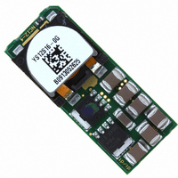
YS12S16-0G
Description
CONVERTER DC-DC 12V 16A SMD
Manufacturer
POWER ONE
Series
Yr
Type
Point of Load (POL) Non-Isolatedr
Datasheet
1.YS12S16-0G.pdf
(27 pages)
Specifications of YS12S16-0G
Output
0.75 ~ 5.5V
Number Of Outputs
1
Power (watts)
88W
Mounting Type
Surface Mount
Voltage - Input
9.6 ~ 14V
Package / Case
6-DIP SMD Module
1st Output
0.75 ~ 5.5 VDC @ 16A
Size / Dimension
1.30" L x 0.53" W x 0.31" H (33mm x 13.5mm x 7.9mm)
Power (watts) - Rated
88W
Operating Temperature
-40°C ~ 85°C
Efficiency
94.8%
Approvals
cUL, EN, UL
Product
Non-Isolated / POL
Output Power
88 W
Input Voltage Range
9.6 V to 14 V
Input Voltage (nominal)
12 V
Output Voltage (channel 1)
0.7525 V to 5.5 V
Output Current (channel 1)
16 A
Package / Case Size
33.02 mm x 13.46 mm x 7.98 mm
Output Type
Regulated
Output Voltage
0.7525 V to 5.5 V
Lead Free Status / RoHS Status
Lead free / RoHS Compliant
3rd Output
-
2nd Output
-
Lead Free Status / Rohs Status
Lead free / RoHS Compliant
Other names
179-2368-2
Available stocks
Company
Part Number
Manufacturer
Quantity
Price

Part Number:
YS12S16-0G
Manufacturer:
POWER-ONE
Quantity:
20 000


voltage source; the value can be chosen depending
on the required output voltage range [k ].
Control voltages with
shown in Table 2.
Protection Features
Input Undervoltage Lockout
Input undervoltage lockout is standard with this
converter. The converter will shut down when the
input voltage drops below a pre-determined voltage;
it will start automatically when Vin returns to a
specified range.
The input voltage must be at least 9.6V (typically 9V)
for the converter to turn on. Once the converter has
been turned on, it will shut off when the input voltage
drops below typically 8.5V.
Output Overcurrent Protection (OCP)
The converter is protected against overcurrent and
short circuit conditions. Upon sensing an over-
current condition, the converter will enter hiccup
mode. Once over-load or short circuit condition is
removed, Vout will return to nominal value.
Overtemperature Protection (OTP)
The converter will shut down under an over-
temperature
overheating caused by operation outside the thermal
derating curves, or operation in abnormal conditions
such as system fan failure. After the converter has
cooled to a safe operating temperature, it will
automatically restart.
MCD10207 Rev. 1.0, 24-Jun-10
R
EXT
V
0-REG
0.7525
1.0
1.2
1.5
1.8
2.0
2.5
3.3
5.0
5.5
External resistor between TRIM pin and
[V]
Table 2: Control Voltage [VDC]
V
condition
CTRL
0.700
0.684
0.670
0.650
0.630
0.617
0.584
0.530
0.417
0.384
(R
EXT
R
EXT
= 0)
to
9.6-14 VDC Input; 0.7525-5.5 VDC Programmable @ 16A
0 and
protect
V
CTRL
(R
-0.097
-0.417
-0.631
-1.164
-2.017
-3.831
-4.364
R
0.700
0.436
0.223
EXT
EXT
itself
= 15K)
15K are
from
Page 7 of 27
YS12S16 DC-DC Converter Data Sheet
Safety Requirements
The
International safety regulatory requirements per
UL60950 and EN60950. The maximum DC voltage
between any two pins is Vin under all operating
conditions. Therefore, the unit has ELV (extra low
voltage) output; it meets SELV requirements under
the condition that all input voltages are ELV.
The converter is not internally fused. To comply with
safety agencies requirements, a recognized fuse
with a maximum rating of 15 Amps must be used in
series with the input line.
Characterization
General Information
The converter has been characterized for many
operational aspects, to include thermal derating
(maximum load current as a function of ambient
temperature and airflow) for vertical mounting,
efficiency, start-up and shutdown parameters, output
ripple and noise, transient response to load step-
change, overload and short circuit.
The figures are numbered as Fig. x.y, where x
indicates the different output voltages, and y
associates with specific plots (y = 1 for the vertical
thermal derating, …). For example, Fig. x.1 will refer
to the vertical thermal derating for all the output
voltages in general.
The following pages contain specific plots or
waveforms associated with the converter. Additional
comments for specific data are provided below.
Test Conditions
All data presented were taken with the converter
soldered to a test board, specifically a 0.060” thick
printed wiring board (PWB) with four layers. The top
and bottom layers were not metalized. The two inner
layers, comprising two-ounce copper, were used to
provide traces for connectivity to the converter.
The lack of metalization on the outer layers as well
as the limited thermal connection ensured that heat
transfer from the converter to the PWB was
minimized. This provides a worst-case but consistent
scenario for thermal derating purposes.
All measurements requiring airflow were made in the
vertical and horizontal wind tunnel facilities using
Infrared (IR) thermography and thermocouples for
thermometry.
converter
www.power-one.com
meets
North
American
and
Related parts for YS12S16-0G
Image
Part Number
Description
Manufacturer
Datasheet
Request
R

Part Number:
Description:
Module DC-DC 1-OUT 0.7525V to 5.5V 16A 88W 6-Pin SMD T/R
Manufacturer:
POWER ONE
Datasheet:
Part Number:
Description:
DC/DC Converters & Regulators
Manufacturer:
POWER ONE
Datasheet:
Part Number:
Description:
DC/DC Converters & Regulators
Manufacturer:
POWER ONE
Datasheet:
Part Number:
Description:
SWITCHING POWER SUPPLIES, SINGLE OUTPUT, 80 WATTS
Manufacturer:
POWER ONE
Datasheet:
Part Number:
Description:
HAS SERIES - 30 WATT
Manufacturer:
POWER ONE
Datasheet:
Part Number:
Description:
SINGLE OUTPUT
Manufacturer:
POWER ONE
Datasheet:

Part Number:
Description:
BRS DC/DC converters(1.5 WATT)
Manufacturer:
Power-One
Datasheet:
Part Number:
Description:
3...15 Watt DC-DC Converter
Manufacturer:
Power-One
Datasheet:
Part Number:
Description:
HBS SERIES - 100 WATT
Manufacturer:
Power-One
Datasheet:
Part Number:
Description:
3...15 Watt DC-DC Converter
Manufacturer:
Power-One
Datasheet:
Part Number:
Description:
BUS DC/DC converters(3 WATT)
Manufacturer:
Power-One
Datasheet: