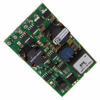
PIM300AZ Lineage Power, PIM300AZ Datasheet - Page 13

PIM300AZ
Manufacturer Part Number
PIM300AZ
Description
MOD PWR ATCA INPUT 5V 300W T/H
Manufacturer
Lineage Power
Series
PIM300Xr
Type
Point of Load (POL) Non-Isolatedr
Datasheet
1.PIM300AZ.pdf
(20 pages)
Specifications of PIM300AZ
Output
5V
Number Of Outputs
1
Power (watts)
300W
Mounting Type
Through Hole
Voltage - Input
0 ~ 75V
Package / Case
Module
1st Output
5 VDC @ 1.6A
Size / Dimension
2.78" L x 1.45" W x 0.50" H (70.6mm x 36.8mm x 12.7mm)
Power (watts) - Rated
300W
Operating Temperature
-5°C ~ 85°C
Efficiency
97%
Approvals
CE, CSA, EN, UL, VDE
Output Power
8 W
Input Voltage Range
- 38 V to - 75 V
Output Voltage (channel 1)
5 V
Output Current (channel 1)
1.6 A
Isolation Voltage
1.5 KV
Package / Case Size
DIP
Output Type
Isolated
Output Voltage
5 V
Product
Isolated
Lead Free Status / RoHS Status
Lead free / RoHS Compliant
3rd Output
-
2nd Output
-
Lead Free Status / Rohs Status
Lead free / RoHS Compliant
Other names
555-1158
CC109122322
CC109122322
Available stocks
Company
Part Number
Manufacturer
Quantity
Price
Company:
Part Number:
PIM300AZ
Manufacturer:
Lineage Power
Quantity:
135
Data Sheet
November 29, 2010
(2) Holdup / Bulk Capacitor Output (72V_CAP)
This output provides the high voltage (nominal 72Vdc)
to charge the C_BULK capacitor(s) to allow the ATCA
board to meet the 5ms, 0Volts transient requirements.
LINEAGE
C
_
HLDP
The -48V_OUT bus may require a fuse
depending on the power and fusing
requirements of the DC/DC converter.
Input filtering of the DC/DC converter is
provided by C_FLTR close to the input pins
of the DC/DC converter(s); additional high
frequency decoupling ceramic capacitors
(0.01 to 0.1μF are recommended for
improved EMI performance.
The maximum C_FLTR capacitance across
all the downstream DC/DC converters
should not exceed 330μF. The
recommended capacitor voltage rating
should be >/= 100Vdc.
The minimum C_FLTR capacitance (200μF)
recommendation is based on meeting the
EMI requirements. Based on end systems
test, the capacitance may be lowered if real
estate is an issue. As a minimum, 50 μF to
100 μF is strongly recommended to stabilize
the line impedance for proper startup of the
DC/DC converter. Refer to the DC/DC
converter’s data sheet for the recommended
capacitor.
The 72V_CAP connects to the +ve terminals
of the C_HLDP capacitors while the –ve
terminals of the C_HLDP connects to the -
48V_OUT bus.
Since the 72V_CAP output is regulated to
72Vdc (+3%/-5%) and the capacitors are off
line during normal operation, the capacitors
may be selected with voltage rating of >/=
80V to minimize the real estate on the board.
The C_HLDP capacitance is dependent on
the system power and the holdup time
requirements based on the following formula
Bleed Resistor (R_Bleed) : The PICMG 3.0
specifications requires a discharge
mechanism (e.g. bleed resistor) to discharge
the holdup/bulk capacitance to less than -
60Vdc and less than 20 joules within one
second of disconnection from the backplane.
This requirement is fulfilled by installing
R_Bleed resistor that is selected based on
the C_HLDP selected in the previous step.
The formula for selecting the resistor is :
R
POWER
(
_
F
Bleed
)
[
P
(
out
(
W
)
)
. 5
{
T
485
holdup
/
(
C
ms
_
)
HLDP
1
7 .
}]
1 /
(
PIM300X Series; ATCA Board Power Input Modules
F
9 .
)
(3) Management Power
(MGMT_PWR)
The MGMT_PWR output is an isolated secondary
voltage (3.3V for PIM300F or 5.0V for PIM300A)
referenced to LOGIC_GND that provides
8W(maximum) power to the IPM Controller for the
ATCA board or to the power up system controller for
other applications.
(4) -48V Feed Loss or Open Fuse Alarm
The -48V_ALARM output is an opto-isolated signal
internally referenced to the LOGIC_GND. The signal
is an open collector output that requires an external
pull up resistor. A 3.3K pull up resistor to 3.3V,
MGMT_PWR (for PIM300F) should suffice. During
normal operation, the signal is LO (opto conducting).
During fault condition, the opto shall stop conducting
and the alarm signal shall assume a HI state.
Safety Considerations
For the system safety agency approval the power
module must be installed in compliance with the
spacing and separation requirements of the end-use
safety agency standards, i.e., UL 60950-1, CSA
C22.2 No. 60950-1-03, and VDE 0850:2001-12
(EN60950-1) Licensed.
(-48V_ALARM)
For 300W and 9.3 ms holdup requirements,
this results in a 2.9 Kohm resistor with 1W
rating.
Worst case power dissipation of R_Bleed
(=2.9Kohms) @ -36V is 0.45W.
The R_Bleed is connected across the
72V_CAP and VRTN_OUT pins of the
PIM300X.
Per PICMG 3.0 Specs, the ATCA board
shall not consume more than 10W of input
power; this includes the standby power of
PIM300X (typically 1.7W) as well as all the
on board DC/DC power converters. It is the
responsibility of the board designer to insure
that this requirement is met prior to power-up
rights have been negotiated with the Shelf
Manager.
The management power is available even
when the input voltage is down to –36Vdc.
No additional output capacitors are required,
but a 22μF tantalum/ceramic and a 0.01 to
0.1μF ceramic capacitors are highly
recommended to contain the switching ripple
and noise.
Higher output capacitance may be required
in case of large input line or output load
transient conditions.
-38 to -75Vdc; 300W Input
13


