NGA10S15050SEC Murata Power Solutions Inc, NGA10S15050SEC Datasheet - Page 3
NGA10S15050SEC
Manufacturer Part Number
NGA10S15050SEC
Description
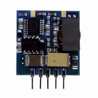
CONV DC/DC 2A 5.0V SIP NON-ISO
Manufacturer
Murata Power Solutions Inc
Series
NGAr
Type
Point of Load (POL) Non-Isolatedr
Datasheet
1.NGA10S15033SC.pdf
(6 pages)
Specifications of NGA10S15050SEC
Number Of Outputs
1
Output
5V
Power (watts)
10W
Mounting Type
Through Hole
Voltage - Input
4.75 ~ 28V
Package / Case
5-SIP Module
1st Output
5 VDC @ 2A
Size / Dimension
0.83" L x 0.22" W x 0.88" H (21.1mm x 5.6mm x 22.4mm)
Power (watts) - Rated
10W
Operating Temperature
-40°C ~ 85°C
Efficiency
95%
Output Power
10 W
Input Voltage Range
4.75 V to 28 V
Output Voltage (channel 1)
5 V
Output Current (channel 1)
2 A
Package / Case Size
SIP
Lead Free Status / RoHS Status
Lead free / RoHS Compliant
3rd Output
-
2nd Output
-
Lead Free Status / Rohs Status
Lead free / RoHS Compliant
Other names
811-1414
Available stocks
Company
Part Number
Manufacturer
Quantity
Price
Company:

Part Number:
NGA10S15050SEC
Manufacturer:
Murata Power Solutions Inc
Quantity:
135


All specifi cations typical at T
1. Accuracy of adjustment is subject to tolerance of resistors and initial output accuracy.
www.murata-ps.com
APPLICATION NOTES
External Capacitance
External capacitors are necessary in order to guarantee stability and full paramet-
ric performance over the full line and load range. All parts have been tested and
characterised using the following values and test circuit.
Voltage trimming
The trimming (adjust) input on the device allows output voltage adjustment to
within ±5%
following equations.
When open circuit, the output will be +5V.
A resistor (R
age between +5V to +1.8V.
A resistor (R
output from +5V to +5.5V.
R
R
1
1
D
U
=
= (22 [1.028V
(
(1.02V
1
D
U
91
of the desired V
) between the trim pin and the output pin will adjust the output volt-
) between the trim pin and the Common pin will adjust the device
O
100μF, 50V
)-1
)
A
O
=25°C, nominal input voltage and rated output current unless otherwise specifi ed.
C
-0.0455
-1])
IN
-1
-0.011
OUT
using a resistor with a value determined by the
Value
100μF, 10V
C
OUT
Test Circuit
Shutdown
When the shutdown pin is shorted to Common, the device’s output will be dis-
abled. To shutdown the device the pin should be taken below 0.8V using either an
open collector pull down or by using isolated delay contacts. To enable the device
output the shutdown pin should be left fl oating or taken no lower than +1.5V to a
maximum of (+28V).
If the shutdown pin is to be connected to a long wire, it is recommended that a
capacitor (10nF) decouples the shutdown pin to Common in order to avoid the risk
of injecting noise into the device circuit.
Technical enquiries email: mk@murata-ps.com, tel: +44 (0)1908 615232
Non-Isolated Wide Input DC/DC Converters
2011-02-23 KDC_NGAC.F02 Page 3 of 6
NGA Series
Related parts for NGA10S15050SEC
Image
Part Number
Description
Manufacturer
Datasheet
Request
R

Part Number:
Description:
POWER OVER ETHERNET MODULE
Manufacturer:
Murata Power Solutions Inc
Datasheet:

Part Number:
Description:
POWER OVER ETHERNET MODULE
Manufacturer:
Murata Power Solutions Inc
Datasheet:

Part Number:
Description:
POWER OVER ETHERNET MODULE
Manufacturer:
Murata Power Solutions Inc
Datasheet:

Part Number:
Description:
POWER OVER ETHERNET MODULE
Manufacturer:
Murata Power Solutions Inc
Datasheet:

Part Number:
Description:
Power Inductors 2.2mH1.4A
Manufacturer:
Murata Power Solutions Inc
Datasheet:

Part Number:
Description:
Power Inductors 6.8uH 3.6A 20mOhm Toroidal SMT
Manufacturer:
Murata Power Solutions Inc
Datasheet:

Part Number:
Description:
Power Inductors Radial1.5mH 150mA
Manufacturer:
Murata Power Solutions Inc
Datasheet:
Part Number:
Description:
Power Inductors 680uH 2.2A 1.3MHz Radial PCB Mounting
Manufacturer:
Murata Power Solutions Inc
Datasheet:
Part Number:
Description:
Power Inductors 6.8mH0.5A
Manufacturer:
Murata Power Solutions Inc
Datasheet:
Part Number:
Description:
Power Inductors 470uH2.7A
Manufacturer:
Murata Power Solutions Inc
Datasheet:

Part Number:
Description:
Transformers 5Vin 5Vout 200mA 4000Vdc 1:1.33 turn
Manufacturer:
Murata Power Solutions Inc
Datasheet:

Part Number:
Description:
POWER SUPPLY
Manufacturer:
Murata Power Solutions Inc
Datasheet:

Part Number:
Description:
DPM LED MINI 2VDC 3.5DIG LP RED
Manufacturer:
Murata Power Solutions Inc
Datasheet:

Part Number:
Description:
CONV DC/DC 1W 5VIN 5VOUT SIP SGL
Manufacturer:
Murata Power Solutions Inc
Datasheet:

Part Number:
Description:
CONV DC/DC 1W 5VIN 3.3V SIP SGL
Manufacturer:
Murata Power Solutions Inc
Datasheet: