LSM2-T/30-D12-C Murata Power Solutions Inc, LSM2-T/30-D12-C Datasheet - Page 2
LSM2-T/30-D12-C
Manufacturer Part Number
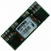
LSM2-T/30-D12-C
Description
CONV DC/DC 125W 30A 12V SMD
Manufacturer
Murata Power Solutions Inc
Series
LSM2r
Type
Point of Load (POL) Non-Isolatedr
Datasheet
1.LSM2-T30-D12-C.pdf
(11 pages)
Specifications of LSM2-T/30-D12-C
Output
0.8 ~ 5V
Number Of Outputs
1
Power (watts)
125W
Mounting Type
Surface Mount
Voltage - Input
8.3 ~ 13.2V
Package / Case
8-DIP SMD Module
1st Output
0.8 ~ 5 VDC @ 30A
Size / Dimension
1.30" L x 0.53" W x 0.34" H (33mm x 13.5mm x 8.6mm)
Power (watts) - Rated
125W
Operating Temperature
-40°C ~ 85°C
Efficiency
94%
Approvals
CSA, cUL, EN, UL
Output Power
150 W
Input Voltage Range
6 V to 14 V
Output Voltage (channel 1)
0.8 V to 5 V
Output Current (channel 1)
30 A
Product
Non-Isolated / POL
Input Voltage (nominal)
12 V
Package / Case Size
SMD
Output Type
Non-Isolated POL
Output Voltage
0.8 V to 5 V
Lead Free Status / RoHS Status
Lead free / RoHS Compliant
3rd Output
-
2nd Output
-
Lead Free Status / Rohs Status
Lead free / RoHS Compliant
Other names
811-1792
811-1792-1
811-1792-1
811-1792-1
811-1792-1
Available stocks
Company
Part Number
Manufacturer
Quantity
Price

Part Number:
LSM2-T/30-D12-C
Manufacturer:
MURATA/村田
Quantity:
20 000


M Typical @ Ta=+25°C. under nominal line voltage and full-load conditions unless noted. Nominal
N Ripple/Noise (R/N) is tested/specifi ed over a 5 Hz to 20 MHz bandwidth and may be reduced by
O These devices have no minimum load requirements and will regulate under no-load conditions.
output is +5 Volts.
adding external fi ltering. R/N is shown at V
Regulation specifi cations describe the output voltage deviation as the line voltage or load is varied
from its nominal/midpoint value to either extreme.
SEQUENCE
Additional
ground/thermal
pads
COMMON
CONTROL
V
INPUT
ON/OFF
TRACK
+INPUT
/
0.8-5
0.8-5
0.8-5
= Unipolar
Low Voltage
0.8-5.0 Volts
30
30
30
OUT
V
R
CC
<= 2.5 Volts.
125
125
125
Current in Amps
CONTROLLER
M
*One phase of two is shown.
15
15
15
PWM
www.murata-ps.com
-
25
25
25
N
/
±0.2%
±0.2%
±0.2%
-
CURRENT
SENSE
P Nominal line voltage, no-load/full-load conditions.
Q LSM2-T/30-D12 effi ciencies are shown at V
R I
➆ If V
➇ LSM2-T/30-D12R-C-CIS models use a 100KΩ resistor between the gate and source of the internal
*
On/Off (Enable) FET controlling the PWM.
OUT
±0.4%
±0.4%
±0.4%
OUT
max. is 30 Amps with V
>3.63V, input range is 7-14V.
-
O
See note 7 above.
(does not claim EU RoHS exemption 7b–lead in solder)
= Installed
REFERENCE &
ERROR AMP
12
12
12
= 6-14 Volts (12V nominal)
= Omitted
OUT
= 0.8 to 3.6 Volts. With V
6-14
6-14
6-14
DOSA-SMT, 30A POL DC/DC Converters
S
210/11.1
210/11.1
210/11.1
OUT
= 5 Volts.
P
OUT
92.5%
92.5%
92.5%
>3.6 Volts, I
Typical topology is shown.
+OUTPUT
+SENSE
TRIM
COMMON
V
OUT
OUT
94%
94%
94%
Q
max. is 25 Amps.
Page 2 of 11
C71, P72
C71, P72
C71, P72
Related parts for LSM2-T/30-D12-C
Image
Part Number
Description
Manufacturer
Datasheet
Request
R

Part Number:
Description:
CONV DC/DC 125W 30A 12V SMD
Manufacturer:
Murata Power Solutions Inc
Datasheet:
Part Number:
Description:
CONV DC/DC 30W 6A 12V SMD
Manufacturer:
Murata Power Solutions Inc
Datasheet:
Part Number:
Description:
CONV DC/DC 30W 6A 12V SMD
Manufacturer:
Murata Power Solutions Inc
Datasheet:

Part Number:
Description:
DC/DC Converter
Manufacturer:
Murata Power Solutions Inc
Datasheet:
Part Number:
Description:
DC/DC Converter
Manufacturer:
Murata Power Solutions Inc
Datasheet:
Part Number:
Description:
CONV DC/DC 19.8W 6A 5V SMD
Manufacturer:
Murata Power Solutions Inc
Datasheet:
Part Number:
Description:
CONV DC/DC 19.8W 6A 5V SMD
Manufacturer:
Murata Power Solutions Inc
Datasheet:
Part Number:
Description:
CONV DC/DC 33W 10A 5V SMD
Manufacturer:
Murata Power Solutions Inc
Datasheet:
Part Number:
Description:
CONV DC/DC 33W 10A 5V SMD
Manufacturer:
Murata Power Solutions Inc
Datasheet:
Part Number:
Description:
CONV DC/DC 50W 10A 12V SMD
Manufacturer:
Murata Power Solutions Inc
Datasheet:

Part Number:
Description:
DC/DC Converter
Manufacturer:
Murata Power Solutions Inc
Datasheet:

Part Number:
Description:
Transformers 5Vin 5Vout 200mA 4000Vdc 1:1.33 turn
Manufacturer:
Murata Power Solutions Inc
Datasheet:

Part Number:
Description:
POWER SUPPLY
Manufacturer:
Murata Power Solutions Inc
Datasheet:

Part Number:
Description:
DPM LED MINI 2VDC 3.5DIG LP RED
Manufacturer:
Murata Power Solutions Inc
Datasheet:

Part Number:
Description:
CONV DC/DC 1W 5VIN 5VOUT SIP SGL
Manufacturer:
Murata Power Solutions Inc
Datasheet: