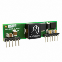
OKX2-T/10-D12P-C Murata Power Solutions Inc, OKX2-T/10-D12P-C Datasheet - Page 5

OKX2-T/10-D12P-C
Manufacturer Part Number
OKX2-T/10-D12P-C
Description
CONVERT DC/DC SIP 50W 0.75-5.5V
Manufacturer
Murata Power Solutions Inc
Series
Okami™ OKX-T/10-D12r
Type
Point of Load (POL) Non-Isolatedr
Specifications of OKX2-T/10-D12P-C
Number Of Outputs
1
Output
0.75 ~ 5.5V
Power (watts)
50W
Mounting Type
Through Hole
Voltage - Input
8.3 ~ 14V
Package / Case
11-SIP Module
1st Output
0.75 ~ 5.5 VDC @ 10A
Size / Dimension
2.00" L x 0.37" W x 0.50" H (50.8mm x 9.4mm x 12.7mm)
Power (watts) - Rated
50W
Efficiency
94.5%
Approvals
cUL, EN, UL
Output Power
55 W
Input Voltage Range
8.3 V to 14 V
Output Voltage (channel 1)
0.7525 V to 5.5 V
Output Current (channel 1)
10 A
Output Voltage (channel 2)
0.7525 V to 5.5 V
Output Current (channel 2)
10 A
Output Voltage (channel 3)
0.7525 V to 5.5 V
Output Current (channel 3)
10 A
Package / Case Size
SIP
Output Voltage
0.7525 V to 5.5 V
Product
Non-Isolated / POL
Dc / Dc Converter O/p Type
Adjustable
No. Of Outputs
1
Input Voltage
8.3V To 14V
Power Rating
50W
Output Current
10A
Approval Bodies
EN / FCC / IEC / UL
Rohs Compliant
Yes
Lead Free Status / RoHS Status
Lead free / RoHS Compliant
Operating Temperature
-
3rd Output
-
2nd Output
-
Lead Free Status / Rohs Status
Lead free / RoHS Compliant
Other names
811-2014-5
Available stocks
Company
Part Number
Manufacturer
Quantity
Price
Part Number:
OKX2-T/10-D12P-C
Manufacturer:
MURATA/村田
Quantity:
20 000
Specifi cation Notes, Cont.:
(7)
(8)
(9)
(10) Regulation specifications describe the deviation as the line input voltage or output load current is varied
(11) Other input or output voltage ranges will be reviewed under scheduled quantity special order.
(12) Maximum PC board temperature is measured with the sensor in the center of the converter.
(13) Do not exceed maximum power specifications when adjusting the output trim.
(14) The maximum output capacitive loads depend on the the Equivalent Series Resistance (ESR) of the external
(15) Do not allow the input voltage to degrade lower than the input undervoltage shutdown voltage at all times.
(16) The outputs are not intended to sink appreciable reverse current.
Output Voltage Adjustment
ing an external trim resistor (Rtrim) between the Trim pin and Ground. The
Rtrim resistor must be a 1/10 Watt precision metal fi lm type, ±1% accuracy
or better with low temperature coeffi cient, ±100 ppm/°C. or better. Mount
the resistor close to the converter with very short leads or use a surface
mount trim resistor.
the specifi ed limits of the output voltage or the converter’s maximum power
rating when applying these resistors. Also, avoid high noise at the Trim
input. However, to prevent instability, you should never connect any capaci-
tors to Trim.
Soldering Guidelines
Murata Power Solutions recommends the specifi cations below when installing these converters. These specifi cations vary depending on the solder type. Exceeding these specifi ca-
tions may cause damage to the product. Be cautious when there is high atmospheric humidity. We strongly recommend a mild pre-bake (100° C. for 30 minutes). Your production
environment may differ; therefore please thoroughly review these guidelines with your process engineers.
For Sn/Ag/Cu based solders:
Maximum Preheat Temperature
Maximum Pot Temperature
Maximum Solder Dwell Time
The output voltage may be adjusted over a limited range by connect-
In the tables opposite, the calculated resistance is given. Do not exceed
“Hiccup” overcurrent operation repeatedly attempts to restart the converter with a brief, full-current output.
If the overcurrent condition still exists, the restart current will be removed and then tried again. This short
current pulse prevents overheating and damaging the converter. Once the fault is removed, the converter
immediately recovers normal operation.
Output noise may be further reduced by adding an external filter. At zero output current, the output may
contain low frequency components which exceed the ripple specification. The output may be operated
indefinitely with no load.
All models are fully operational and meet published specifications, including “cold start” at –40°C.
from a nominal midpoint value to either extreme.
output capacitor and, to a lesser extent, the distance and series impedance to the load. Larger caps will
reduce output noise but may change the transient response. Newer ceramic caps with very low ESR may
require lower capacitor values to avoid instability. Thoroughly test your capacitors in the application. Please
refer to the Output Capacitive Load Application Note.
Otherwise, you risk having the converter turn off. The undervoltage shutdown is not latching and will
attempt to recover when the input is brought back into normal operating range.
Wave Solder Operations for through-hole mounted products (THMT)
115° C.
270° C.
7 seconds
For Sn/Pb based solders:
Maximum Preheat Temperature
Maximum Pot Temperature
Maximum Solder Dwell Time
www.murata-ps.com
105° C.
250° C.
6 seconds
Adjustable DOSA 10/16-Amp SIP DC/DC Converters
OKX2-T/10-D12, -T/16-D12
Resistor Trim Equation, D12 models:
5.0 V.
3.3 V.
2.5 V.
2.0 V.
1.8 V.
1.5 V.
1.2 V.
1.0 V.
0.7525 V.
R
Output Voltage
TRIM
(Ω) = ________________
Technical enquiries email: sales@murata-ps.com, tel:
OKX
V
OUT
10500
– 0.7525V
T/10 & T/16-D12 Series
1.472
3.122
5.009
7.416
9.024
13.05
22.46
41.424
∞ (open)
Calculated Rtrim (KΩ)
MDC_MDC_OKX2_T10T16.A04 Page 5 of 15
–1000
+1 508 339 3000


