LTM4600IV#PBF Linear Technology, LTM4600IV#PBF Datasheet - Page 10
LTM4600IV#PBF
Manufacturer Part Number
LTM4600IV#PBF
Description
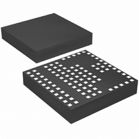
IC DC/DC UMODULE 10A 104-LGA
Manufacturer
Linear Technology
Series
µModuler
Type
Point of Load (POL) Non-Isolatedr
Datasheet
1.LTM4600EVPBF.pdf
(24 pages)
Specifications of LTM4600IV#PBF
Design Resources
LTM4600 Spice Model
Output
0.6 ~ 5 V
Number Of Outputs
1
Power (watts)
50W
Mounting Type
Surface Mount
Voltage - Input
4.5 ~ 20V
Package / Case
104-LGA
1st Output
0.6 ~ 5 VDC @ 10A
Size / Dimension
0.59" L x 0.59" W x 0.11" H (15mm x 15mm x 2.8mm)
Power (watts) - Rated
50W
Operating Temperature
-40°C ~ 85°C
Efficiency
92%
Lead Free Status / RoHS Status
Lead free / RoHS Compliant
3rd Output
-
2nd Output
-
Available stocks
Company
Part Number
Manufacturer
Quantity
Price


APPLICATIONS INFORMATION
LTM4600
the module input pins in the PCB layout to minimize the
trace inductance and high frequency AC noise.
Output Capacitors
The LTM4600 is designed for low output voltage ripple. The
bulk output capacitors C
effective series resistance (ESR) to meet the output voltage
ripple and transient requirements. C
tantalum capacitor, low ESR polymer capacitor or ceramic
capacitor (X5R or X7R). The typical capacitance is 200μF
if all ceramic output capacitors are used. The internally
optimized loop compensation provides suffi cient stability
margin for all ceramic capacitors applications. Additional
output fi ltering may be required by the system designer,
if further reduction of output ripple or dynamic transient
spike is required. Refer to Table 2 for an output capaci-
tance matrix for each output voltage Droop, peak to peak
deviation and recovery time during a 5A/μs transient with
a specifi c output capacitance.
Fault Conditions: Current Limit and Over current
Foldback
The LTM4600 has a current mode controller, which inher-
ently limits the cycle-by-cycle inductor current not only in
steady state operation, but also in transient.
To further limit current in the event of an over load condi-
tion, the LTM4600 provides foldback current limiting. If the
output voltage falls by more than 50%, then the maximum
output current is progressively lowered to about one sixth
of its full current limit value.
10
OUT
is chosen with low enough
OUT
can be low ESR
Soft-Start and Latchoff with the RUN/SS pin
The RUN/SS pin provides a means to shut down the
LTM4600 as well as a timer for soft-start and over-cur-
rent latchoff. Pulling the RUN/SS pin below 0.8V puts
the LTM4600 into a low quiescent current shutdown (I
≤ 75μA). Releasing the pin allows an internal 1.2μA cur-
rent source to charge up the timing capacitor C
LTM4600, there is an internal 1000pF capacitor from RUN/
SS pin to ground. If RUN/SS pin has an external capacitor
C
When the voltage on RUN/SS pin reaches 1.5V, the LTM4600
internal switches are operating with a clamping of the
maximum output inductor current limited by the RUN/SS
pin total soft-start capacitance. As the RUN/SS pin voltage
rises to 3V, the soft-start clamping of the inductor current
is released.
V
There are restrictions in the maximum V
down ratio that can be achieved for a given input voltage.
These contraints are shown in the Typical Performance
Characteristics curves labeled “V
Ratio”. Note that additional thermal derating may apply. See
the Thermal Considerations and Output Current Derating
sections of this data sheet.
After the controller has been started and given adequate
SS_EXT
IN
t
DELAY
to V
OUT
to ground, the delay before starting is about:
=
Step-Down Ratios
1.2μA
1.5V
• (C
SS_EXT
+ 1000pF)
IN
to V
OUT
IN
to V
Step-Down
SS
OUT
. Inside
step
4600fc
Q
Related parts for LTM4600IV#PBF
Image
Part Number
Description
Manufacturer
Datasheet
Request
R

Part Number:
Description:
10A High Effi ciency DC/DC ?Module
Manufacturer:
LINER [Linear Technology]
Datasheet:

Part Number:
Description:
IC DC/DC UMODULE 10A 104-LGA
Manufacturer:
Linear Technology
Datasheet:

Part Number:
Description:
CD ROM LINEARVIEW DATASHEETS
Manufacturer:
Linear Technology

Part Number:
Description:
Standalone Linear Li-Ion Battery Charger with Thermal Regulation in ThinSOT
Manufacturer:
Linear Technology Corporation
Datasheet:
Part Number:
Description:
Low noise, high frequency, 8th order linear phase lowpass filter
Manufacturer:
Linear Technology Corporation
Datasheet:
Part Number:
Description:
Manufacturer:
Linear Technology Corporation
Datasheet:
Part Number:
Description:
Manufacturer:
Linear Technology Corporation
Datasheet:
Part Number:
Description:
Manufacturer:
Linear Technology Corporation
Datasheet:
Part Number:
Description:
Manufacturer:
Linear Technology Corporation
Datasheet:
Part Number:
Description:
Manufacturer:
Linear Technology Corporation
Datasheet:
Part Number:
Description:
Manufacturer:
Linear Technology Corporation
Datasheet:
Part Number:
Description:
Manufacturer:
Linear Technology Corporation
Datasheet:
Part Number:
Description:
Dual and Quad, JFET Input Precision High Speed Op Amps
Manufacturer:
Linear Technology Corporation
Datasheet:
Part Number:
Description:
Manufacturer:
Linear Technology Corporation
Datasheet:
Part Number:
Description:
1, 2, 6 and 8 Channel, 10-Bit Serial I/O Data Acquisition Systems
Manufacturer:
Linear Technology Corporation
Datasheet: