HSMF-C157 Avago Technologies US Inc., HSMF-C157 Datasheet - Page 6
HSMF-C157
Manufacturer Part Number
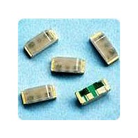
HSMF-C157
Description
LED CHIP GRN/ORN 3.2X2.7MM SMD
Manufacturer
Avago Technologies US Inc.
Datasheet
1.HSMF-C155.pdf
(8 pages)
Specifications of HSMF-C157
Package / Case
1210 (3225 Metric)
Viewing Angle
170°
Color
Green, Orange
Millicandela Rating
15mcd Green, 8mcd Orange
Current - Test
20mA
Wavelength - Dominant
572nm, 604nm
Wavelength - Peak
570nm, 605nm
Voltage - Forward (vf) Typ
2.2V Green, 2.2V Orange
Lens Type
Diffused
Lens Style/size
Rectangle, 2.7mm x 2mm
Size / Dimension
3.20mm L x 2.70mm W
Height
1.10mm
Mounting Type
Surface Mount
Resistance Tolerance
572nm, 604nm
Led Size
3.2 mm x 2.7 mm
Illumination Color
Orange, Green
Lens Color/style
Diffused
Operating Voltage
2.2 V
Wavelength
572 nm, 604 nm
Luminous Intensity
15 mcd, 8 mcd
Mounting Style
SMD/SMT
Operating Current
20 mA
Lens Dimensions
2 mm x 2.7 mm
Lens Shape
Rectangular
Maximum Operating Temperature
+ 85 C
Minimum Operating Temperature
- 30 C
Peak Wavelength
570 nm, 605 nm
Led Color
Orange / Green
Luminous Intensity / Color
O 8mcd / G 15mcd
Led Mounting
SMD
Wavelength / Color
O 604nm / G 572nm
Rohs Compliant
Yes
Bulb Size
2mm X 2.7mm
Lead Free Status / RoHS Status
Lead free / RoHS Compliant
Luminous Flux @ Current - Test
-
Lead Free Status / Rohs Status
Lead free / RoHS Compliant
Available stocks
Company
Part Number
Manufacturer
Quantity
Price
Company:

Part Number:
HSMF-C157
Manufacturer:
AVAGO
Quantity:
40 000
Company:
Part Number:
HSMF-C157
Manufacturer:
AVAGO
Quantity:
50 000


Figure 7. Recommended Pb free reflow soldering profile.
6
Figure 5. Relative intensity vs. angle for HSMF-C153, C155, C156, C157 and C158.
Figure 2. Forward current vs. forward voltage.
100
1.00
0.90
0.80
0.70
0.60
0.50
0.40
0.30
0.20
0.10
0.1
10
1
0
-90
1.5
217 °C
200 °C
150 °C
V
-80
F
- FORWARD VOLTAGE - V
-70
1.7
3 °C/SEC. MAX.
3 °C/SEC. MAX.
-60
HER
ORANGE
60 - 120 SEC.
YELLOW
-50
255 - 260 °C
1.9
-40
-30
TIME
2.1
-20
GREEN
-10
ANGLE
2.3
0
100 SEC. MAX.
(Acc. to J-STD-020C)
10 - 30 SEC.
10
6 °C/SEC. MAX.
Figure 3. Luminous intensity vs. forward
current (all colors).
20 30
1.6
1.2
0.8
0.4
0
0
40
I
F
50
- FORWARD CURRENT - mA
60
10
70
80
20
90
30
Figure 8. Recommended solder pad pattern.
Note: 1. All dimensions in millimeters (inches).
Figure 6. Recommended reflow soldering profile.
(0.059)
40
1.5
140-160°C
Figure 4. Maximum forward current vs. ambient
temperature.
(0.079)
35
30
25
20
15
10
5
0
2.0
0
OVER 2 MIN.
T
Rθ
Rθ
4°C/SEC.
10 SEC. MAX.
A
230 °C MAX.
MAX.
J-A
J-A
- AMBIENT TEMPERATURE - ° C
20
(0.059)
= 600 ° C/W
= 800 ° C/W
1.5
TIME
40
1.0 (0.039)
1.0 (0.039)
60
0.4 (0.016)
80
4°C/SEC. MAX.
3°C/SEC. MAX.
100
Related parts for HSMF-C157
Image
Part Number
Description
Manufacturer
Datasheet
Request
R

Part Number:
Description:
LED CHIP GAP GREEN/YELLOW SMD
Manufacturer:
Avago Technologies US Inc.
Datasheet:

Part Number:
Description:
LED BICOLOR YLW/GN DIFF 1210 SMD
Manufacturer:
Avago Technologies US Inc.
Datasheet:

Part Number:
Description:
LED IND RED/GRN TOP MOUNT 4PLCC
Manufacturer:
Avago Technologies US Inc.
Datasheet:
Part Number:
Description:
LED IND YLW/YGRN TOP MOUNT 4PLCC
Manufacturer:
Avago Technologies US Inc.
Datasheet:

Part Number:
Description:
LED CHIP RGB 2.5X1.0X1.0MM SMD
Manufacturer:
Avago Technologies US Inc.
Datasheet:

Part Number:
Description:
LED CHIPLED AMB/BLUE DIFF 0603
Manufacturer:
Avago Technologies US Inc.
Datasheet:
Part Number:
Description:
LED CHIPLED RED/GRN DIFF 0603
Manufacturer:
Avago Technologies US Inc.
Datasheet:
Part Number:
Description:
LED RED/GREEN/BLUE 40MCD 5V SMD
Manufacturer:
Avago Technologies US Inc.
Datasheet:
Part Number:
Description:
Standard LED - SMD Red/YGrn/Blue Tri-Color
Manufacturer:
Avago Technologies US Inc.
Datasheet:

Part Number:
Description:
LED CHIP RGB 3.2X2.7X1.1MM SMD
Manufacturer:
Avago Technologies US Inc.
Datasheet:

Part Number:
Description:
LED BICOLOR GN/HER DIFF 1210 SMD
Manufacturer:
Avago Technologies US Inc.
Datasheet:

Part Number:
Description:
LED BICOLOR HER/GN DIFF 0603 SMD
Manufacturer:
Avago Technologies US Inc.
Datasheet:
Part Number:
Description:
LED IND RED/YLW TOP MOUNT 4PLCC
Manufacturer:
Avago Technologies US Inc.
Datasheet:
Part Number:
Description:
LED IND RED/EGRN TOP MOUNT 4PLCC
Manufacturer:
Avago Technologies US Inc.
Datasheet:
Part Number:
Description:
LED IND ORN/YGRN TOP MOUNT 4PLCC
Manufacturer:
Avago Technologies US Inc.
Datasheet: