ASMT-BA20-AS000 Avago Technologies US Inc., ASMT-BA20-AS000 Datasheet - Page 3
ASMT-BA20-AS000
Manufacturer Part Number
ASMT-BA20-AS000
Description
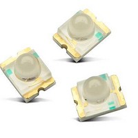
LAMP PCB POLYLED ALINGAP AMB SMD
Manufacturer
Avago Technologies US Inc.
Datasheet
1.ASMT-BA20-AS000.pdf
(6 pages)
Specifications of ASMT-BA20-AS000
Package / Case
1209 (3224 Metric)
Viewing Angle
15°
Color
Amber
Millicandela Rating
750mcd
Current - Test
20mA
Wavelength - Dominant
590nm
Wavelength - Peak
592nm
Voltage - Forward (vf) Typ
2V
Lens Type
Clear
Lens Style/size
Round, 1.8mm
Size / Dimension
3.20mm L x 2.40mm W
Height
2.40mm
Mounting Type
Surface Mount
Resistance Tolerance
590nm
Led Size
3.2 mm x 2.4 mm
Illumination Color
Amber
Lens Color/style
Untinted Non-Diffused
Operating Voltage
2 V
Wavelength
590 nm
Luminous Intensity
750 mcd
Mounting Style
SMD/SMT
Operating Current
20 mA
Lens Dimensions
1.8 mm
Lens Shape
Dome
Maximum Operating Temperature
+ 85 C
Minimum Operating Temperature
- 40 C
Peak Wavelength
592 nm
Led Color
Amber
Luminous Intensity @ Test
750mcd
Wavelength Typ
590nm
Forward Current @ Test
20mA
Forward Current If Max
30mA
Forward Voltage @ Test
2V
Led Mounting
SMD
Rohs Compliant
Yes
Lead Free Status / RoHS Status
Lead free / RoHS Compliant
Luminous Flux @ Current - Test
-
Lead Free Status / RoHS Status
Lead free / RoHS Compliant, Lead free / RoHS Compliant


Optical Characteristics at T
Notes:
1. The luminous intensity IV is measured at the peak of the spatial radiation pattern which may not be aligned with the mechanical axis of the LED
2. The dominant wavelength, λ
3. θ
Light Intensity (I
Tolerance : ±15%
Color Bin Limits
Amber Color Bins
Tolerance : ±1 nm
Notes:
1. Bin categories are established for classification of products. Products may not be available in all categories. Please contact your Avago
Part Number
AlInGaP Amber
AlInGaP Green
AlInGaP Red
InGaN Blue
Bin ID
P
Q
R
S
T
U
V
W
X
Y
Bin ID
1
2
3
4
5
6
package.
representative for information on current available bins.
1/2
is the off-axis angle where the luminous intensity is ½ the peak intensity.
V
[1]
[1]
) Bin Limits
Luminous Intensity
I
A
Minimum
Minimum
V [1]
1125.00
1800.00
2850.00
= 25
Dominant Wavelength (nm)
d
112.50
180.00
285.00
450.00
715.00
582.0
584.5
587.0
589.5
592.0
594.5
45.00
71.50
, is derived from the CIE Chromaticity Diagram and represents the perceived color of the device.
[1]
(mcd) @ 20mA
°
Typ.
C
750
650
650
650
Intensity (mcd)
Maximum
Maximum
1125.00
1800.00
2850.00
4500.00
112.50
180.00
285.00
450.00
715.00
584.5
587.0
589.5
592.0
594.5
597.0
71.50
Peak Wavelength
λpeak (nm)
Typ.
592
565
635
470
Green Color Bins
Tolerance : ±1 nm
Red Color Bins
Tolerance : ±1 nm
Blue Color Bins
Tolerance : ±1 nm
Bin ID
1
2
3
4
5
Bin ID
-
Bin ID
1
2
3
4
Dominant Wavelength
[1]
[1]
[1]
λ
d [2]
Typ.
590
569
626
468
Dominant Wavelength (nm)
Dominant Wavelength (nm)
Dominant Wavelength (nm)
(nm)
Minimum
Minimum
Minimum
561.5
564.5
567.5
570.5
573.5
620.0
460.0
465.0
470.0
475.0
2θ
Viewing Angle
1/2 [3]
Maximum
Maximum
Maximum
Typ.
564.5
567.5
570.5
573.5
576.5
635.0
15
15
15
15
465.0
470.0
475.0
480.0
(Degrees)
Related parts for ASMT-BA20-AS000
Image
Part Number
Description
Manufacturer
Datasheet
Request
R

Part Number:
Description:
LED IND 0.5W R/G/B 4PLCC
Manufacturer:
Avago Technologies US Inc.
Datasheet:
Part Number:
Description:
LED HIGH BRIGHTNESS RGB 6PLCC
Manufacturer:
Avago Technologies US Inc.
Datasheet:

Part Number:
Description:
OPTOCOUPLER GATE DRV 2A 16-SOIC
Manufacturer:
Avago Technologies US Inc.
Datasheet:
Part Number:
Description:
OPTOCOUPLER 2CH 2.5A 16-SOIC
Manufacturer:
Avago Technologies US Inc.
Datasheet:

Part Number:
Description:
OPTOCOUPLER GATE DRV 0.4A 16SOIC
Manufacturer:
Avago Technologies US Inc.
Datasheet:

Part Number:
Description:
OPTOCOUPLER 2.0A 250KHZ 8-DIP
Manufacturer:
Avago Technologies US Inc.
Datasheet:

Part Number:
Description:
OPTOCOUPLER 2.0A 250KHZ GW 8-SMD
Manufacturer:
Avago Technologies US Inc.
Datasheet:

Part Number:
Description:
OPTOCOUPLER 2CH 15MBD 3.3V 8SOIC
Manufacturer:
Avago Technologies US Inc.
Datasheet:
Part Number:
Description:
OPTOCOUPLER DARL-OUT 8-DIP
Manufacturer:
Avago Technologies US Inc.
Datasheet:
Part Number:
Description:
OPTOCOUPLER IGBT DRIVE 0.4A 8DIP
Manufacturer:
Avago Technologies US Inc.
Datasheet:
Part Number:
Description:
OPTOCOUPLER DARL-OUT 8-DIP
Manufacturer:
Avago Technologies US Inc.
Datasheet:

Part Number:
Description:
OPTOCOUPLER 1CH 1MBS 8-SMD GW
Manufacturer:
Avago Technologies US Inc.
Datasheet:
Part Number:
Description:
OPTOCOUPLER GATE DRIVER 8-DIP
Manufacturer:
Avago Technologies US Inc.
Datasheet:

Part Number:
Description:
OPTOCOUPLER GATE DRIVER 8-SMD
Manufacturer:
Avago Technologies US Inc.
Datasheet:

Part Number:
Description:
OPTOCOUPLER PHOTOTRANS 4-SMD
Manufacturer:
Avago Technologies US Inc.
Datasheet: