LXM1624-12-41 Microsemi Analog Mixed Signal Group, LXM1624-12-41 Datasheet - Page 2
LXM1624-12-41
Manufacturer Part Number
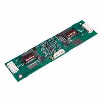
LXM1624-12-41
Description
MOD INVERTER CCFL DUAL 4W 12V
Manufacturer
Microsemi Analog Mixed Signal Group
Series
LXM1624-12-4xr
Type
Inverters for CCFL and UV Lampsr
Datasheet
1.LXM1624-12-41.pdf
(6 pages)
Specifications of LXM1624-12-41
Voltage - Input
12V
Output
1500V
Size / Dimension
4.53" L x 1.18" W x 0.26" H (115mm x 30mm x 6.5mm)
Mounting Type
Chassis Mount
Lead Free Status / RoHS Status
Contains lead / RoHS non-compliant


Copyright © 2002
Rev. 1.0b, 2005-01-17
This module has been designed to operate over a wide range of input and output conditions. However, best efficiency and performance
will be obtained if the module is operated under the condition listed in the ‘R.C.’ column. Min. and Max. columns indicate values beyond
which the inverter, although operational, will not function optimally.
Unless otherwise specified, the following specifications apply over the recommended operating condition and ambient temperature of
25°C except where otherwise noted.
¹ The minimum V
Input Signal Voltage (V
Input Power ....................................................................................................................................................................... 10W
Output Voltage, no load ............................................................................................................ Internally Limited to 1500V
Output Current ............................................................................................................................7.5mA
Output Power (each output) ............................................................................................................................................. 4.0W
Input Signal Voltage ( SLEEP Input) ..................................................................................................................... -0.3V to V
Input Signal Voltage (BRITE) ...............................................................................................................................-0.3V to 5.5V
Ambient Operating Temperature, zero airflow.....................................................................................................-20°C to 70°C
Operating Relative Humidity, non-condensing ................................................................................................................
Storage Temperature Range...............................................................................................................................-40°C to 85°C
Note 1: Exceeding these ratings could cause damage to the device. All voltages are with respect to Ground. Currents are positive into, negative out of specified
² The inverter is capable of a lower output current than may be recommended by the panel manufacturer. It is the user’s responsibility to set the
minimum brightness (BRITE) input at or above the panel specification for minimum current.
Output Power (each output)
Linear BRITE Control Input Voltage Range¹
Lamp Operating Voltage
Lamp Current (Full Brightness)
Operating Ambient Temperature Range
Input Supply Voltage Range (Fully Regulated
Lamp Current)
Input Supply Voltage Range (Functional)
OUTPUT PIN CHARACTERISTICS
Full Bright Lamp Current (each output)
Full Bright Lamp Current (each output)
Full Bright Lamp Current (each output)
Full Bright Lamp Current (each output)
Output Current Lamp to Lamp
Deviation
Min. Average Lamp Current
(each output)
Lamp Start Voltage
Operating Frequency
terminal.
I N T E G R A T E D
Parameter
BRT ADJ
Parameter
voltage depends on the panel characteristics, depending on the panel it can vary from 0.65V to 0.9V
11861 Western Avenue, Garden Grove, CA. 92841, 714-898-8121, Fax: 714-893-2570
IN1
R E C O M M E N D E D O P E R A T I N G C O N D I T I O N S ( R . C . )
).....................................................................................................................................-0.3V to 15V
A B S O L U T E M A X I M U M R A T I N G S
P R O D U C T S
E L E C T R I C A L C H A R A C T E R I S T I C S
Symbol
I
I
I
I
I
LL%DEV
I
L(MAX)
L(MAX)
L(MAX)
L(MAX)
L(MIN)
V
f
O
LS
V
I
V
I
V
I
V
I
V
I
V
I
-20°C < T
V
SET1
SET1
SET1
SET1
SET1
SET1
BRT_ADJ
BRT_ADJ
BRT_ADJ
BRT_ADJ
BRT_ADJ
BRT_ADJ
BRT_ADJ
Integrated Products
= Ground, I
= Ground, I
= Open, I
= Open, I
= Open, I
= I
Microsemi
Symbol
SET2
V
> 2.0V
> 2.0V
> 2.0V
> 2.0V
> 2.0V
=0.65V
= 2.5V
V
I
BRT_ADJ
OLAMP
PanelMatch™
A
V
P
LAMP
T
< 70°C, V
IN1
= Ground
O
A
SET2
SET2
SET2
DC
DC
DC
DC
DC
DC
DC
Test Conditions
SET2
SET2
, SLEEP > 2.0V, V
, SLEEP > 2.0V, V
, SLEEP > 2.0V, V
, SLEEP > 2.0V, V
, SLEEP > 2.0V, V
, SLEEP > 2.0V, V
, SLEEP > 2.0V, V
= Ground
= Open
= Open
12V Dual 4W CCFL Programmable Inverter Module
= Ground
= Open
IN1
Recommended Operating Conditions
0.65 to 0.9
> 10.8V
10.8
10.2
Min
350
-20
5
DC
P
RODUCTION
IN1
IN1
IN1
IN1
IN1
IN1
IN1
( N O T E 1 )
= 12V
= 12V
= 12V
= 12V
= 12V
= 12V
= 12V
R.C.
440
3.5
12
12
DC
DC
DC
DC
DC
DC
D
ATASHEET
1250
Min
4.5
5.0
5.5
6.0
76
LXM1624-12-4x
Max
13.2
13.8
530
4.0
2.0
6.5
RMS
70
LXM1624-12-4x
1400
Typ
(Internally Limited)
5.5
6.5
80
2²
5
6
3
Max
5.5
6.0
6.5
7.0
10
83
mA
Units
V
°C
W
RMS
V
V
≤
RMS
90%
RMS
Units
mA
mA
mA
mA
mA
V
IN1
kHz
%
RMS
Page 2
RMS
RMS
RMS
RMS
RMS
Related parts for LXM1624-12-41
Image
Part Number
Description
Manufacturer
Datasheet
Request
R

Part Number:
Description:
MOD INVERTER CCFL DUAL 4W 12V
Manufacturer:
Microsemi Analog Mixed Signal Group
Datasheet:

Part Number:
Description:
MOD INVERTER CCFL DUAL 4W 12V
Manufacturer:
Microsemi Analog Mixed Signal Group
Datasheet:

Part Number:
Description:
MOD INVERTER CCFL DUAL 6W 12V
Manufacturer:
Microsemi Analog Mixed Signal Group
Datasheet:

Part Number:
Description:
MOD INVERTER CCFL DUAL 6W 12V
Manufacturer:
Microsemi Analog Mixed Signal Group
Datasheet:
Part Number:
Description:
MOD INVERTER CCFL DUAL 6W 12V
Manufacturer:
Microsemi Analog Mixed Signal Group
Datasheet:
Part Number:
Description:
MOD INVERTER CCFL DUAL 6W 12V
Manufacturer:
Microsemi Analog Mixed Signal Group
Datasheet:

Part Number:
Description:
IC USB LINE TERM EMI/ESD SC70-6
Manufacturer:
Microsemi Analog Mixed Signal Group
Datasheet:
Part Number:
Description:
IC USB LINE TERM EMI/ESD SC70-6
Manufacturer:
Microsemi Analog Mixed Signal Group
Datasheet:

Part Number:
Description:
IC TERM SCSI 9LINE MODE 24TSSOP
Manufacturer:
Microsemi Analog Mixed Signal Group
Datasheet:

Part Number:
Description:
IC TERM SCSI 9LINE MODE 28TSSOP
Manufacturer:
Microsemi Analog Mixed Signal Group
Datasheet:

Part Number:
Description:
IC TERM SCSI 9LINE LVD 24TSSOP
Manufacturer:
Microsemi Analog Mixed Signal Group
Datasheet:
Part Number:
Description:
IC TERM SCSI 9LINE MODE 36QSOP
Manufacturer:
Microsemi Analog Mixed Signal Group
Datasheet:

Part Number:
Description:
IC USB LINE TERM EMI/ESD SOT23-6
Manufacturer:
Microsemi Analog Mixed Signal Group
Datasheet:

Part Number:
Description:
IC USB LINE TERM EMI/ESD SOT23-6
Manufacturer:
Microsemi Analog Mixed Signal Group
Datasheet:

Part Number:
Description:
IC USB EMI FLTR ESD PROT SOT23-6
Manufacturer:
Microsemi Analog Mixed Signal Group