LXMG1813-12-61S Microsemi Analog Mixed Signal Group, LXMG1813-12-61S Datasheet - Page 4
LXMG1813-12-61S
Manufacturer Part Number
LXMG1813-12-61S
Description
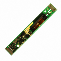
MOD INVERTER CCFL 6W 12V PROG
Manufacturer
Microsemi Analog Mixed Signal Group
Series
PanelMatch™r
Type
Inverters for CCFL and UV Lampsr
Datasheet
1.LXMG1813-12-61S.pdf
(7 pages)
Specifications of LXMG1813-12-61S
Voltage - Input
12V
Output
1600V
Size / Dimension
4.33" L x 0.63" W x 0.24" H (110mm x 16mm x 6mm)
Mounting Type
Chassis Mount
Lead Free Status / RoHS Status
Lead free / RoHS Compliant


Copyright © 2008
Rev 1.0, 2008-11-14
CN3 for LXMG1813-12-61S and -62S (JST SM02(8.0)B-BHS-1-TB(LF)(SN) ; Yeon Ho 20015WR-05A00, SM02B-BHSS-1-TB(LF)(SN) ; Yeon Ho
R1.0
* If driven by a logic signal it should be open collector or open drain only, not a voltage source.
CN3-1
CN3-2
C
ONN
TM
CN1
Ground
Ground
3.5mm
(Pin 7)
0.138in.
Open*
Open*
SET
1
11861 Western Avenue, Garden Grove, CA. 92841, 800-877-6458, 714-898-8121, Fax: 714-893-2570
1.0mm
0.0394in.
19.5mm
0.768in.
±0.1
P
V
V
IN
LO
HI
PCB tolerances ± 0.5mm , M3 recommended mounting screws
H
G
CN2
OLE
16mm
ROUNDED
0.63in.
All dimensions are in millimeters, inches are for reference only
3.18
High voltage connection to high side of lamp. Connect to lamp terminal with shortest lead length. DO NOT
connect to Ground.
Connection to low side of lamp. Connect to lamp terminal with longer lead length.
DO NOT connect to Ground
MM
M
Ground
Ground
(Pin 8)
OUNTING
±.08 DIA.
Open*
Open*
35001WR-02A00) or equivalent
SET
9mm ±0.2
0.354in.
93.5mm
F U N C T I O N A L P I N D E S C R I P T I O N
3.68in.
2
P H Y S I C A L D I M E N S I O N S
110mm
4.33in.
OUTPUT CURRENT SETTINGS
Analog Mixed Signal Group
L X M G 1 8 1 3 - 1 2 - 6 x S
74mm ±0.2mm
®
Microsemi
2.91in
PanelMatch™ VEasyLIT™ LXMG1813-12-6xS
T A B L E 1
12V 6W CCFL Programmable Inverter Module
DESCRIPTION
P
Nominal Output Current
12.5mm
RODUCTION
0.492in
3.18
M
OUNTING
Weight: (9g) typ
MM
±.08 DIA.
CN3
7.0mA
6.0mA
5.0mA
4.0mA
CN2
H
OLE
D
.
ATASHEET
High Voltage is present at high
and the high side of the output
directions) on the component
connector, please provide at
side of transformer, its core
least 3 mm clearance (in all
6.0mm Max
conductor when mounting
side of the board to any
0.236in.
Warning
Page 4
Related parts for LXMG1813-12-61S
Image
Part Number
Description
Manufacturer
Datasheet
Request
R

Part Number:
Description:
MOD INVERTER CCFL 6W 12V PROG
Manufacturer:
Microsemi Analog Mixed Signal Group
Datasheet:

Part Number:
Description:
MOD INVERTER CCFL 6W 12V PROG
Manufacturer:
Microsemi Analog Mixed Signal Group
Datasheet:

Part Number:
Description:
MOD INVERTER CCFL 6W 12V PROG
Manufacturer:
Microsemi Analog Mixed Signal Group
Datasheet:

Part Number:
Description:
IC USB LINE TERM EMI/ESD SC70-6
Manufacturer:
Microsemi Analog Mixed Signal Group
Datasheet:

Part Number:
Description:
IC USB LINE TERM EMI/ESD SC70-6
Manufacturer:
Microsemi Analog Mixed Signal Group
Datasheet:

Part Number:
Description:
IC TERM SCSI 9LINE MODE 24TSSOP
Manufacturer:
Microsemi Analog Mixed Signal Group
Datasheet:

Part Number:
Description:
IC TERM SCSI 9LINE MODE 28TSSOP
Manufacturer:
Microsemi Analog Mixed Signal Group
Datasheet:

Part Number:
Description:
IC TERM SCSI 9LINE LVD 24TSSOP
Manufacturer:
Microsemi Analog Mixed Signal Group
Datasheet:
Part Number:
Description:
IC TERM SCSI 9LINE MODE 36QSOP
Manufacturer:
Microsemi Analog Mixed Signal Group
Datasheet:
Part Number:
Description:
IC AMP AUDIO PWR 10W STER 44SSOP
Manufacturer:
Microsemi Analog Mixed Signal Group
Datasheet:

Part Number:
Description:
IC CHARGER BATT USB LI-ION 20MLP
Manufacturer:
Microsemi Analog Mixed Signal Group
Datasheet:

Part Number:
Description:
IC LED DRIVER LINEAR 6-MLP
Manufacturer:
Microsemi Analog Mixed Signal Group
Datasheet:

Part Number:
Description:
IC LED DRIVR WT/CLR BCKLGT 8-MLP
Manufacturer:
Microsemi Analog Mixed Signal Group
Datasheet:

Part Number:
Description:
IC LED DRVR WT/CLR BCKLGT 8-MSOP
Manufacturer:
Microsemi Analog Mixed Signal Group
Datasheet:

Part Number:
Description:
IC LED DRVR WT/CLR BCKLT 14TSSOP
Manufacturer:
Microsemi Analog Mixed Signal Group
Datasheet: