LXMG1811-05-62S Microsemi Analog Mixed Signal Group, LXMG1811-05-62S Datasheet - Page 6
LXMG1811-05-62S
Manufacturer Part Number
LXMG1811-05-62S
Description
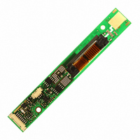
MOD INVERTER CCFL 6W 5V PROG
Manufacturer
Microsemi Analog Mixed Signal Group
Series
PanelMatch™r
Type
Inverters for CCFL and UV Lampsr
Datasheet
1.LXMG1811-05-61S.pdf
(7 pages)
Specifications of LXMG1811-05-62S
Voltage - Input
5V
Output
1650V
Size / Dimension
4.33" L x 0.63" W x 0.24" H (110mm x 16mm x 6mm)
Mounting Type
Chassis Mount
Lead Free Status / RoHS Status
Lead free / RoHS Compliant


Copyright © 2008
Rev 1.0, 2008-11-14
500k
TM
(Output current set to maximum)
Figure 2 – Max Output Current
11861 Western Avenue, Garden Grove, CA. 92841, 800-877-6458, 714-898-8121, Fax: 714-893-2570
BRITE
SLEEP
Figure 1 – Brightness Control
SET
BRITE
SLEEP
SET
NC
(SET
H
H
L
L
1
LXMG1811-05-6xS
1
L=GND; H=Open
LXMG1811-05-6xS
SET
1
and SET
H
H
SET
L
L
NC
2
5V
V
2
5V
V
IN
IN
4.0mA
5.0mA
6.0mA
7.0mA
GND
2
GND
Inputs)
RMS
RMS
RMS
RMS
V
V
V
V
LO
LO
HI
HI
T Y P I C A L A P P L I C A T I O N
Analog Mixed Signal Group
TUBE
CCFL
CCFL
TUBE
®
Microsemi
PanelMatch™ VEasyLIT™ LXMG1811-05-6xS
5V 6W CCFL Programmable Inverter Module
It is recommended to use LXMG1811-05-6xS only with
the LXMG1800_LS external light sensor assembly.
500k potentiometer may be added to the inverter’s BRITE
input pin to allow a degree of manual override to the light
sensor. Adjustment of the potentiometer will only dim the
display further; it cannot increase the maximum brightness
level set by the light sensor. If full manual control of
dimming is required by the application we recommend the
use of the LXMG1811-05-6x (non-S) version.
If you need to turn the inverter ON/OFF remotely, connect
to TTL logic signal to the
Connect V
V
Never connect V
lamp current regulation. If both lamp wires have heavy
high voltage insulation, connect the longest wire to V
This wire is typically white.
Use the SET
desired maximum output current. Using these two pins in
combination allows the inverter to match a wide variety of
panels from different manufacturers. Generally the best
lamp lifetime correlates with driving the CCFL at the
manufacture’s nominal current setting. However the SET
and SET
current to the maximum allowable output current to
increase panel brightness at the expense of some reduced
lamp life.
Although the SET pins are designed such that just leaving
them open or grounding them is all that is needed to set the
output current, they can also be actively set. Using an open
collector or open drain logic signal will allow you to
reduce the lamp current for situations where greater dim
range is required. Since the dim ratio is a factor of both
the burst duty cycle and the peak output current, using this
technique the effective dim ratio can be increased greater
than the burst duty cycle alone. Conversely, the SET inputs
could be used to overdrive the lamp temporarily to
facilitate faster lamp warm up at initial lamp turn on. Of
course any possible degradation on lamp life from such
practices is the user’s responsibility since not all lamps are
designed to be overdriven.
output is open (lamp disconnected or broken) or shorted
the inverter will attempt to strike the lamp up to about two
seconds, after which (without success) the inverter will
shutdown. In this mode the inverter will draw about 5mA
from VIN. In order to restart the inverter it is necessary to
toggle the sleep input or cycle the V
The inverter has a built-in fault timeout function. If the
LO
to the low voltage wire (wire with thinner insulation).
P
2
RODUCTION
inputs allow the user the flexibility to adjust the
HI
1
to high voltage wire from the lamp. Connect
and SET
LO
to circuit ground as this will defeat
2
D
(see Figure 2) inputs to select the
SLEEP
ATASHEET
input.
IN
input supply.
LO
A
Page 6
1
.
Related parts for LXMG1811-05-62S
Image
Part Number
Description
Manufacturer
Datasheet
Request
R

Part Number:
Description:
MOD INVERTER CCFL 6W 5V PROG
Manufacturer:
Microsemi Analog Mixed Signal Group
Datasheet:

Part Number:
Description:
MOD INVERTER CCFL 6W 5V PROG
Manufacturer:
Microsemi Analog Mixed Signal Group
Datasheet:
Part Number:
Description:
MOD INVERTER CCFL 6W 5V PROG
Manufacturer:
Microsemi Analog Mixed Signal Group
Datasheet:

Part Number:
Description:
IC USB LINE TERM EMI/ESD SC70-6
Manufacturer:
Microsemi Analog Mixed Signal Group
Datasheet:

Part Number:
Description:
IC USB LINE TERM EMI/ESD SC70-6
Manufacturer:
Microsemi Analog Mixed Signal Group
Datasheet:

Part Number:
Description:
IC TERM SCSI 9LINE MODE 24TSSOP
Manufacturer:
Microsemi Analog Mixed Signal Group
Datasheet:

Part Number:
Description:
IC TERM SCSI 9LINE MODE 28TSSOP
Manufacturer:
Microsemi Analog Mixed Signal Group
Datasheet:

Part Number:
Description:
IC TERM SCSI 9LINE LVD 24TSSOP
Manufacturer:
Microsemi Analog Mixed Signal Group
Datasheet:
Part Number:
Description:
IC TERM SCSI 9LINE MODE 36QSOP
Manufacturer:
Microsemi Analog Mixed Signal Group
Datasheet:

Part Number:
Description:
IC USB LINE TERM EMI/ESD SOT23-6
Manufacturer:
Microsemi Analog Mixed Signal Group
Datasheet:

Part Number:
Description:
IC USB LINE TERM EMI/ESD SOT23-6
Manufacturer:
Microsemi Analog Mixed Signal Group
Datasheet:

Part Number:
Description:
IC USB EMI FLTR ESD PROT SOT23-6
Manufacturer:
Microsemi Analog Mixed Signal Group
Part Number:
Description:
IC USB LINE TERM EMI/ESD SOT23-6
Manufacturer:
Microsemi Analog Mixed Signal Group
Datasheet:
Part Number:
Description:
IC AMP AUDIO PWR 10W STER 44SSOP
Manufacturer:
Microsemi Analog Mixed Signal Group
Datasheet:

Part Number:
Description:
IC CHARGER BATT USB LI-ION 20MLP
Manufacturer:
Microsemi Analog Mixed Signal Group
Datasheet: