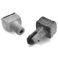
HFBR-2505CZ Avago Technologies US Inc., HFBR-2505CZ Datasheet - Page 4

HFBR-2505CZ
Manufacturer Part Number
HFBR-2505CZ
Description
RCVR FIBER OPTIC INTERBUS-S
Manufacturer
Avago Technologies US Inc.
Datasheet
1.HFBR-2505AZ.pdf
(11 pages)
Specifications of HFBR-2505CZ
Data Rate
2MBd
Voltage - Supply
4.75 V ~ 5.25 V
Current - Supply
6.2mA
Applications
General Purpose
Data Rate Max
0.01Gbps
Data Transmission Distance
400m
Wavelength Typ
650nm
Peak Reflow Compatible (260 C)
Yes
Leaded Process Compatible
Yes
Connector Type
SMA, INTERBUS-S
Lead Free Status / RoHS Status
Lead free / RoHS Compliant
Power - Minimum Receivable
-
Lead Free Status / RoHS Status
Lead free / RoHS Compliant, Lead free / RoHS Compliant
Figure 1. Typical forward voltage vs. drive
current
Peak Output Power
-0°C to +70°C unless otherwise noted.
Model Number
HFBR-1505AZ SERCOS
HFBR-1515BZ PROFIBUS
HFBR-1505CZ INTERBUS-S
Notes:
10. Pins 1 and 4 are for mounting and retaining purposes, but are electrically connected; pins 5 and 6 are electrically isolated. It is recommended
11. Output power with 200 µm hard clad silica optical fiber assumes a typical –10.5 dB difference compared to 1 mm plastic optical fiber.
4
1. Typical data at 25˚C.
2. Optical power measured at the end of 0.5 meters of 1 mm diameter plastic optical fiber with a large area detector.
3. Minimum and maximum values for P
4. Thermal resistance is measured with the transmitter coupled to a connector assembly and fiber, and mounted on a printed circuit board.
5. To further reduce the thermal resistance, the cathode trace should be made as large as is consistent with good RF circuit design.
6. For I
7. 1.6 mm below seating plane.
8. Minimum peak output power at 25˚C is –5.3 dBm (POF) and –16.0 dBm (HCS
9. Optical power measured at the end of 1 meter of 1 mm diameter plastic or 200 µm hard clad silica optical fiber with a large area detector.
2.5
2.3
2.1
1.9
1.7
1.5
compensation which reduces the variation in P
that pins 1, 4, 5, and 6 all be connected to ground to reduce coupling of electrical noise.
1
I
F,DO
F,PK
- TRANSMITTER DRIVE CURRENT - mA
> 60 mA, the duty factor must maintain I
10
-40 ˚C
25 ˚C
70 ˚C
0 ˚C
85 ˚C
Symbol
T
100
P
over temperature are based on a fixed drive current. The recommended drive circuit has temperature
T
Figure 2. Typical normalized optical power vs.
drive current
T
F,AVG
over temperature, refer to Figures 4 and 6.
-10
-20
-30
-40
10
0
–10.5
–18.0
–10.5
–18.0
–16.9
I
1
–7.5
–7.5
–6.2
F,DO
Min.
≤ 60 mA and pulse width ≤ 1 µs.
- TRANSMITTER DRIVE CURRENT - mA
Max.
–5.5
–3.5
–5.5
–3.5
–8.5
–8.5
–10
0.0
10
-40 ˚C
25 ˚C
®
) for 1505C series only.
85 ˚C
dBm
Unit
100
Condition
POF, I
POF, I
HCS
POF, I
POF, I
HCS
POF, I
HCS
Figure 3. Typical normalized optical spectra
®
®
®
1.4
1.2
1.0
0.8
0.6
0.4
0.2
, I
, I
, I
F, dc
F, dc
F, dc
F, dc
F, dc
0
610
F, dc
F, dc
F, dc
= 35 mA
= 60 mA
= 35 mA
= 60 mA
= 60 mA
= 60 mA
= 60 mA
= 60 mA
630
WAVELENGTH Ð nm
650
-40 ˚C
Reference
Notes 2, 3, 11
Figure 2
Notes 2, 3, 11
Figure 2
Notes 3, 8, 9
Figure 2
0 ˚C
25 ˚C
70 ˚C
85 ˚C
670
690


