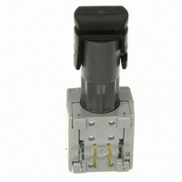
HFBR-2416Z Avago Technologies US Inc., HFBR-2416Z Datasheet - Page 24

HFBR-2416Z
Manufacturer Part Number
HFBR-2416Z
Description
RECEIVER FIBER OPT 125MHZ ANA ST
Manufacturer
Avago Technologies US Inc.
Specifications of HFBR-2416Z
Data Rate
160MBd
Voltage - Supply
1.84V
Current - Supply
100mA
Product
Receiver
Wavelength
820 nm
Lead Free Status / RoHS Status
Lead free / RoHS Compliant
Applications
-
Power - Minimum Receivable
-
Lead Free Status / Rohs Status
Lead free / RoHS Compliant
Other names
516-2059
Available stocks
Company
Part Number
Manufacturer
Quantity
Price
Company:
Part Number:
HFBR-2416Z
Manufacturer:
Avago Technologies
Quantity:
135
Dynamic Characteristics
-40 °C to +85 °C; 4.75 V d Supply Voltage d 5.25 V; R
Notes:
1. 2.0 mm from where leads enter case.
2. Typical specifications are for operation at T
3. For 200 μm HCS fibers, typical responsivity will be 6 mV/mW. Other parameters will change as well.
4. Pin #2 should be ac coupled to a load ³ 510 ohm. Load capacitance must be less than 5 pF.
5. Measured with a 3 pole Bessel filter with a 75 MHz, -3 dB bandwidth. Recommended receiver filters for various bandwidths are provided in
6. Overdrive is defined at PWD = 2.5 ns.
7. D is the effective diameter of the detector image on the plane of the fiber face. The numerical value is the product of the actual detector di-
8. Measured with a 10 ns pulse width, 50% duty cycle, at the 50% amplitude point of the waveform.
9. Percent overshoot is defined as:
10. The conversion factor for the rise time to bandwidth is 0.41 since the HFBR-24x6Z has a second order bandwidth limiting characteristic.
Figure 14. Recommended ac Coupled Receiver Circuit. (See AB 78 and AN 1038 for more information.)
24
Parameter
Rise/Fall Time 10% to 90%
Pulse Width Distortion
Overshoot
Bandwidth (Electrical)
Bandwidth - Rise Time Product
CAUTION: The small junction sizes inherent to the design of these components increase the components’ susceptibility to damage
from electrostatic discharge (ESD). It is advised that normal static precautions be taken in handling and assembly of these compo-
nents to prevent damage and/or degradation which may be induced by ESD.
Application Bulletin 78.
ameter and the lens magnification.
(
V
PK
V
−
100%
V
100%
)
x
100%
30 pF
0.1 μF
Symbol
t
PWD
BW
r
, t
f
A
= +25 °C and V
6
2
3 & 7
10 Ω
Min
LOAD
R LOADS
500 Ω MIN.
CC
= 511 :, C
= +5 V dc.
POST
AMP
Typ
3.3
0.4
2
125
0.41
2
LOAD
Max
6.3
2.5
= 5 pF unless otherwise specified
Units
ns
ns
%
Hz • s
MHz
OUTPUT
LOGIC
+5 V
Conditions
P
P
P
t
-3 dB Electrical
Note 10
r
R
R
R
= 1.5 ns
= 100 μW peak
= 150 μW peak
= 5 μW peak,
Reference
Figure 17
Note 8,
Figure 16
Note 9


