HCMS-3907 Avago Technologies US Inc., HCMS-3907 Datasheet - Page 19
HCMS-3907
Manufacturer Part Number
HCMS-3907
Description
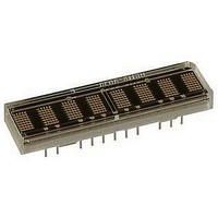
LED DISPLAY 5X7 4CHAR 3.8MM GRN
Manufacturer
Avago Technologies US Inc.
Series
HCMS-39xxr
Datasheet
1.HCMS-3906.pdf
(22 pages)
Specifications of HCMS-3907
Millicandela Rating
*
Internal Connection
*
Size / Dimension
*
Color
Green
Configuration
*
Voltage - Forward (vf) Typ
*
Package / Case
12-DIP
Display Type
Alphanumeric
Number Of Digits/alpha
4
Digit/alpha Size
0.15" (3.8mm)
Character Format
Dot Matrix
Character Size
3.81mm
Led Color
Green
Luminous Intensity
1mcd
No. Of Digits / Alpha
4
Display Area Width
17.78mm
Display Area Height
10.16mm
Number Of Digits
4
Illumination Color
Green
Wavelength
574 nm
Operating Voltage
3.3 V
Maximum Operating Temperature
+ 85 C
Minimum Operating Temperature
- 40 C
Lead Free Status / RoHS Status
Lead free / RoHS Compliant
Common Pin
-
Lead Free Status / Rohs Status
Details


19
Appendix B. Electrical
Considerations
Current Calculations
The peak and average display
current requirements have a
significant impact on power
supply selection. The maximum
peak current is calculated with
Equation 3 in Table 3.
Table 3. Equations.
Equation 1:
T
Where: T
Equation 2:
P
Where:
Equation 3:
I
Where:
Equation 4:
I
(See Variable Definitions above)
PEAK
LED
J
D
MAX = T
= (N * I
(AVG) = N * I
Duty Factor = 1/8 * Osccyc/64
= M * 20 * I
Osc cyc = number of ON oscillator cycles per row
J
V
PIXEL
I
I
I
I
MAX = maximum IC junction temperature
LOGIC
LOGIC
A
R
PIXEL
PIXEL
PEAK
+ P
P
P
T
JA
20 = maximum number of LEDs on per IC
M = number of ICs in the system
N = number of pixels on (maximum 4 char * 5 * 7 = 140)
A
D
D
* Duty Factor * V
D
PIXEL
= ambient temperature surrounding the display
= thermal resistance from the IC junction to ambient
= total power dissipation
= total power dissipation
= peak pixel current.
= IC logic current
= logic supply voltage
= maximum instantaneous peak current for the display
= peak current for one LED
PIXEL
* R
JA
* 1/8 * (oscillator cycles)/64
LED
) + I
The average current required by
the display can be calculated with
Equation 4 in Table 3.
The power supply has to be able
to supply I
supply I
The range on V
on this supply without signifi-
cantly changing the display
brightness.
LOGIC
* V
LED
LOGIC
PEAK
(AVG) continuously.
LED
transients and
allows noise
V
The display uses two independent
electrical systems. One system is
used to power the display’s logic
and the other to power the
display’s LEDs. These two
systems keep the logic supply
clean.
Separate electrical systems allow
the voltage applied to V
V
pendently. Thus, V
from 0 to 5.5 V without affecting
either the Dot or the Control
Registers. V
between 3.1 to 5.5 V without
much noticeable variation in light
output to the human eyes. There
is also no pixel mismatch
observed.
The intensity of the light output
takes a plunge if operated less
than 3.1 V. There is also no pixel
mismatch observed at voltage as
low as 2.6 V. However, operating
below 3.1 V is not recommended.
Dimming the display by pulse
width modulating V
recommended.
V
without affecting either the
displayed message or the display
intensity. However, operating
below 3 V may change the timing
and logic levels and may cause
Dot and Control Registers to be
altered. Thus, operation of the
display below 3.0 V is not
recommended.
The logic ground is internally
connected to the LED ground by
a substrate diode. This diode
becomes forward biased and
conducts when the logic ground is
0.4 V greater than the LED
ground. The LED ground and the
logic ground should be connected
to a common ground, which can
withstand the current introduced
by the switching LED drivers.
When separate ground
LOGIC
LOGIC
LOGIC
and V
to be varied inde-
can vary from 3.0 to 5.5 V
LED
LED
can be varied
Considerations
LED
LED
can vary
LED
is also not
and
Related parts for HCMS-3907
Image
Part Number
Description
Manufacturer
Datasheet
Request
R

Part Number:
Description:
LED DISPLAY 5X7 4CHAR 5MM GREEN
Manufacturer:
Avago Technologies US Inc.
Datasheet:

Part Number:
Description:
LED DISPLAY 5X7 8CHAR 3.8MM YLW
Manufacturer:
Avago Technologies US Inc.
Datasheet:

Part Number:
Description:
LED DISPLAY 5X7 4CHAR 3.8MM YLW
Manufacturer:
Avago Technologies US Inc.
Datasheet:

Part Number:
Description:
LED DISPLAY 5X7 4CHAR 3.8MM ORN
Manufacturer:
Avago Technologies US Inc.
Datasheet:

Part Number:
Description:
LED DISPL 5X7 4CHAR 3.8MM ALGAAS
Manufacturer:
Avago Technologies US Inc.
Datasheet:
Part Number:
Description:
LED DISPLAY 5X7 4CHAR 3.8MM RED
Manufacturer:
Avago Technologies US Inc.
Datasheet:
Part Number:
Description:
LED DISPLAY 5X7 4CHAR 3.8MM ORN
Manufacturer:
Avago Technologies US Inc.
Datasheet:
Part Number:
Description:
LED DISPLAY 5X7 4CHAR 3.8MM YLW
Manufacturer:
Avago Technologies US Inc.
Datasheet:
Part Number:
Description:
LED DISPLAY 5X7 4CHAR 5MM YLW
Manufacturer:
Avago Technologies US Inc.
Datasheet:
Part Number:
Description:
LED DISPLAY 5X7 4CHAR 5MM ORN
Manufacturer:
Avago Technologies US Inc.
Datasheet:
Part Number:
Description:
LED DISPLAY 5X7 4CHAR 5MM GRN
Manufacturer:
Avago Technologies US Inc.
Datasheet:
Part Number:
Description:
LED DISPLAY 5X7 4CHAR 5MM RED
Manufacturer:
Avago Technologies US Inc.
Datasheet:
Part Number:
Description:
LED DISPLAY 5X7 4CHAR 3.8MM RED
Manufacturer:
Avago Technologies US Inc.
Datasheet:
Part Number:
Description:
LED DISPLAY 5X7 4CHAR 5MM GRN
Manufacturer:
Avago Technologies US Inc.
Datasheet:
Part Number:
Description:
LED DISPLAY 5X7 8CHAR 3.8MM ORN
Manufacturer:
Avago Technologies US Inc.
Datasheet: