DS1921K# Maxim Integrated Products, DS1921K# Datasheet - Page 9
DS1921K#
Manufacturer Part Number
DS1921K#
Description
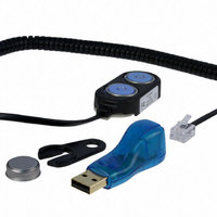
KIT IBUTTON THERMOCHRON
Manufacturer
Maxim Integrated Products
Series
iButton®r
Specifications of DS1921K#
Lead Free Status / RoHS Status
Lead free / RoHS Compliant
Memory Size
-
Memory Type
-
Lead Free Status / Rohs Status
Lead free / RoHS Compliant
Available stocks
Company
Part Number
Manufacturer
Quantity
Price


Figure 3. 64-Bit Lasered ROM
Figure 4. 1-Wire CRC Generator
using a polynomial generator consisting of a shift regis-
ter and XOR gates as shown in Figure 4. The polynomi-
al is X
1-Wire CRC is available in Application Note 27:
Understanding and Using Cyclic Redundancy Checks
with Maxim iButton Products .
The Shift register bits are initialized to 0. Then, starting
with the least significant bit of the family code, one bit
at a time is shifted in. After the 8th bit of the family code
has been entered, the serial number is then entered.
After the 48th bit of the serial number has been
entered, the Shift register contains the CRC value.
Shifting in the 8 bits of CRC returns the Shift register to
all zeros.
X
0
8
+ X
MSB
MSB
STAGE
1ST
5
+ X
CRC CODE
X
1
8-BIT
4
_______________________________________________________________________________________
+ 1. Additional information about the
STAGE
2ND
LSB
X
2
MSB
STAGE
3RD
X
3
STAGE
4TH
POLYNOMIAL = X
48-BIT SERIAL NUMBER
X
4
8
+ X
5
STAGE
Figure 5 shows the DS1921G memory map. The 4096-
bit general-purpose SRAM makes up pages 0 to 15.
The timekeeping, control, and counter registers fill
page 16, called register page (see Figure 6). Pages 17,
18, and 19 are assigned to storing the alarm time-
stamps and durations. The temperature histogram bins
begin at page 64 and use up to four pages. The tem-
perature-logging memory covers pages 128 to 191.
Memory pages 20 to 63, 68 to 127, and 192 to 255 are
reserved for future extensions. The scratchpad is an
additional page that acts as a buffer when writing to the
SRAM memory or the register page. The memory
pages 17 and higher are read only for the user. They
are written to or erased solely under the supervision of
the on-chip control logic.
5TH
+ X
4
+ 1
Thermochron iButton
X
5
STAGE
6TH
LSB
X
6
MSB
STAGE
7TH
8-BIT FAMILY CODE
(21h)
X
INPUT DATA
7
STAGE
8TH
LSB
LSB
Memory
X
8
9
Related parts for DS1921K#
Image
Part Number
Description
Manufacturer
Datasheet
Request
R

Part Number:
Description:
MAX7528KCWPMaxim Integrated Products [CMOS Dual 8-Bit Buffered Multiplying DACs]
Manufacturer:
Maxim Integrated Products
Datasheet:
Part Number:
Description:
Single +5V, fully integrated, 1.25Gbps laser diode driver.
Manufacturer:
Maxim Integrated Products
Datasheet:
Part Number:
Description:
Single +5V, fully integrated, 155Mbps laser diode driver.
Manufacturer:
Maxim Integrated Products
Datasheet:
Part Number:
Description:
VRD11/VRD10, K8 Rev F 2/3/4-Phase PWM Controllers with Integrated Dual MOSFET Drivers
Manufacturer:
Maxim Integrated Products
Datasheet:
Part Number:
Description:
Highly Integrated Level 2 SMBus Battery Chargers
Manufacturer:
Maxim Integrated Products
Datasheet:
Part Number:
Description:
Current Monitor and Accumulator with Integrated Sense Resistor; ; Temperature Range: -40°C to +85°C
Manufacturer:
Maxim Integrated Products
Part Number:
Description:
TSSOP 14/A�/RS-485 Transceivers with Integrated 100O/120O Termination Resis
Manufacturer:
Maxim Integrated Products
Part Number:
Description:
TSSOP 14/A�/RS-485 Transceivers with Integrated 100O/120O Termination Resis
Manufacturer:
Maxim Integrated Products
Part Number:
Description:
QFN 16/A�/AC-DC and DC-DC Peak-Current-Mode Converters with Integrated Step
Manufacturer:
Maxim Integrated Products
Part Number:
Description:
TDFN/A/65V, 1A, 600KHZ, SYNCHRONOUS STEP-DOWN REGULATOR WITH INTEGRATED SWI
Manufacturer:
Maxim Integrated Products
Part Number:
Description:
Integrated Temperature Controller f
Manufacturer:
Maxim Integrated Products
Part Number:
Description:
SOT23-6/I�/45MHz to 650MHz, Integrated IF VCOs with Differential Output
Manufacturer:
Maxim Integrated Products
Part Number:
Description:
SOT23-6/I�/45MHz to 650MHz, Integrated IF VCOs with Differential Output
Manufacturer:
Maxim Integrated Products
Part Number:
Description:
EVALUATION KIT/2.4GHZ TO 2.5GHZ 802.11G/B RF TRANSCEIVER WITH INTEGRATED PA
Manufacturer:
Maxim Integrated Products
Part Number:
Description:
QFN/E/DUAL PCIE/SATA HIGH SPEED SWITCH WITH INTEGRATED BIAS RESISTOR
Manufacturer:
Maxim Integrated Products
Datasheet: