IL388T Vishay, IL388T Datasheet
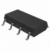
OPTOCOUPLER LINEAR AC DC 8SOP

IL388T

Manufacturer Part Number
IL388T
Description
OPTOCOUPLER LINEAR AC DC 8SOP
Manufacturer
Vishay
Datasheet

Specifications of IL388T

Number Of Channels
2
Input Type
DC
Voltage - Isolation
2130VDC
Current Transfer Ratio (min)
0.69% @ 2mA
Current Transfer Ratio (max)
1.31% @ 2mA
Output Type
Transistor with Base
Mounting Type
Surface Mount
Package / Case
8-SOP
Current Transfer Ratio
0.7 %
Forward Current
10 mA
Isolation Voltage
2130 Vrms
Maximum Rise Time
350 ns
Output Device
Photodiode
Configuration
1 Channel
Maximum Forward Diode Voltage
2.1 V
Maximum Reverse Diode Voltage
3 V
Maximum Input Diode Current
30 mA
Maximum Power Dissipation
250 mW
Maximum Operating Temperature
+ 75 C
Minimum Operating Temperature
0 C
Lead Free Status / RoHS Status
Lead free / RoHS Compliant
Voltage - Output
-
Current - Output / Channel
-
Current - Dc Forward (if)
-
Vce Saturation (max)
-
Lead Free Status / RoHS Status
Lead free / RoHS Compliant, Lead free / RoHS Compliant
DESCRIPTION
The IL388 family of linear optocoupler consist of an IRLED
optically coupled to two photodiodes. The emitter is located
such that both photodiodes receive approximately an equal
amount of infrared light. The diodes produce a proportional
amount of photocurrents. The ratio of the photocurrents
stays constant with high accuracy when either the LED
current changes or the ambient temperature changes. Thus
one can control the output photodiode current.
The IL388 optocouplers can be used with the aid of
operational amplifiers in closed loop conditions to achieve
highly linearly and electrically AC and or DC signals
amplifiers.
Note
For additional information on the available options refer to option information.
Document Number: 83625
Rev. 1.5, 28-Nov-07
ORDER INFORMATION
PART
IL388
ABSOLUTE MAXIMUM RATINGS
PARAMETER
INPUT
Reverse voltage
Forward current
Surge current pulse width < 10 µs
Power dissipation
Derate linearly from 25 °C
Junction temperature
OUTPUT
Reverse voltage
Power dissipation
Derate linearly from 25 °C
Junction temperature
i179085
Linear Optocoupler, PCMCIA Package
B1
C1
K
A
For technical questions, contact: optocoupler.answers@vishay.com
1
2
3
4
K1
K2
7
6
5
8 C2
B2
N.C
N.C
TEST CONDITION
FEATURES
• 2.3 mm high SMD package
• High sensitivity (K1) at low operating LED
• Couples AC and DC signals
• Low input-output capacitance
• Isolation test voltage, 2130 V
• Low distortion, below - 80 db
• 0.4 mm internal insulation thickness
• Component in accordance to RoHS 2002/95/EC and
APPLICATIONS
• Optical DAA for V.34 FAX/modem PCMCIA cards
• Digital telephone line isolation
current
WEEE 2002/96/EC
Couples AC and DC signals, SOP-8
SYMBOL
P
P
V
I
V
I
T
T
PK
diss
diss
F
R
R
j
j
REMARKS
Vishay Semiconductors
DC
VALUE
≤ 0.65
≤ 150
≤ 150
≤ 100
≤ 100
≤ 3.0
≤ 2.0
≤ 30
≤ 15
≤ 50
www.vishay.com
mW/°C
mW/°C
UNIT
IL388
mW
mW
mA
mA
°C
°C
V
V
1

Related parts for IL388T

IL388T Summary of contents

Page 1

... Derate linearly from 25 °C Junction temperature OUTPUT Reverse voltage Power dissipation Derate linearly from 25 °C Junction temperature Document Number: 83625 For technical questions, contact: optocoupler.answers@vishay.com Rev. 1.5, 28-Nov-07 FEATURES • 2.3 mm high SMD package • High sensitivity (K1) at low operating LED 7 ...

Page 2

... Minimum and maximum values were tested requierements. Typical values are characteristics of the device and are the result of engineering evaluations. Typical values are for information only and are not part of the testing requirements. www.vishay.com For technical questions, contact: optocoupler.answers@vishay.com 2 Linear Optocoupler, PCMCIA Package ...

Page 3

... PACKAGE DIMENSIONS in inches (millimeters) Pin One ID 0.230 (5.8) 0.220 (5.6) ISO Method A 0.043 (1.09) 0.033 (0.83) 0.050 (1.25) Typ. i178013 Document Number: 83625 For technical questions, contact: optocoupler.answers@vishay.com Rev. 1.5, 28-Nov-07 MIN. 0.690 0.765 0.851 0.945 1.051 1.169 0.225 (5.7) 0.336 (8.4) ...

Page 4

... The Montreal Protocol (1987) and its London Amendments (1990) intend to severely restrict the use of ODSs and forbid their use within the next ten years. Various national and international initiatives are pressing for an earlier ban on these substances. Vishay Semiconductor GmbH has been able to use its policy of continuous improvements to eliminate the use of ODSs listed in the following documents. ...

Page 5

... Vishay product could result in personal injury or death. Customers using or selling Vishay products not expressly indicated for use in such applications their own risk and agree to fully indemnify and hold Vishay and its distributors harmless from and against any and all claims, liabilities, expenses and damages arising or resulting in connection with such use or sale, including attorneys fees, even if such claim alleges that Vishay or its distributor was negligent regarding the design or manufacture of the part ...

Related keywords