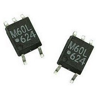
ACPL-M60L-000E Avago Technologies US Inc., ACPL-M60L-000E Datasheet

ACPL-M60L-000E
Specifications of ACPL-M60L-000E
Available stocks
Related parts for ACPL-M60L-000E
ACPL-M60L-000E Summary of contents
Page 1
... Small Outline, 5 Leads, High CMR, High Speed, Logic Gate Optocouplers Data Sheet Description The ACPL-M60L is an optically coupled gate that com- bines a GaAsP light emitting diode and an integrated high gain photo detector. The output of the detector open collector Schottky-clamped transistor. The internal shield provides a guaranteed common mode transient immunity specification of 15 kV/µ ...
Page 2
... Ordering Information ACPL-xxxx is UL Recognized with 3750 Vrms for 1 minute per UL1577 and is approved under CSA Component Ac- ceptance Notice #5, File CA 88324. Option RoHS Part Number Compliant Package ACPL-M60L -000E SO-5 -500E To order, choose a part number from the part number column and combine with the desired option from the option column to form an order entry ...
Page 3
Package Outline Drawing M60L 4.4 ± 0.1 XXX (0.173 ± 0.004) 3.6 ± 0.1* (0.142 ± 0.004) 2.5 ± 0.1 (0.098 ± 0.004) 1.27 BSC (0.050) DIMENSIONS IN MILLIMETERS (INCHES) * MAXIMUM MOLD FLASH ON EACH SIDE IS 0.15 mm ...
Page 4
Solder Reflow Temperature Profile 300 PREHEATING RATE 3°C + 1°C/–0.5°C/SEC. REFLOW HEATING RATE 2.5°C ± 0.5°C/SEC. 200 160°C 150°C 140°C 3°C + 1°C/–0.5°C 100 PREHEATING TIME 150° SEC. ROOM TEMPERATURE Note: Non-halide flux should ...
Page 5
Insulation and Safety Related Specifications Parameter Minimum External Air Gap (Clearance) Minimum External Tracking Path (Creepage) Minimum Internal Plastic Gap (Clearance) Tracking Resistance Isolation Group (per DIN VDE 0109) Absolute Maximum Ratings (No Derating Required up to 85˚C) Parameter Storage ...
Page 6
Electrical Specifications Over recommended Operating Condition (T All Typicals 3 25° Parameter Symbol High Level Output Current Input Threshold I TH Current Low Level Output Voltage ...
Page 7
Switching Specifications Over recommended temperature (T All Typicals 25˚ 3 Parameter Symbol Propagation Delay t PLH Time to High Output Level Propagation Delay t PHL Time to Low Output Level Pulse Width ...
Page 8
... ACPL-M60L H Common Mode Transient Immunity Logic Low |CM | ACPL-M60L L Common Mode Transient Immunity Notes: 1. Peaking circuits may produce transient input currents mA maximum pulse width, provided average current does not exceed 20 mA. 2. Peaking circuits may produce transient input currents mA maximum pulse width, provided average current does not exceed 15 mA. 3. Derate linearly above +80˚ ...
Page 9
350 KΩ KΩ KΩ -60 -40 - 100 ...
Page 10
I F PULSE GEN Ω INPUT 3 MONITORING GND NODE APPROXIMATELY 15 pF WHICH INCLUDES L PROBE AND STRAY WIRING CAPACITANCE. ...
Page 11
350 Ω -60 -40 - 100 60 T – TEMPERATURE – Figure 8. Typical pulse ...


