6N136(F) Toshiba, 6N136(F) Datasheet
6N136(F)
Specifications of 6N136(F)


Related parts for 6N136(F)


6N136(F) Summary of contents
Page 1
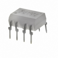
... TOSHIBA Photocoupler GaAℓAs Ired & Photo IC Digital Logic Isolation. Line Receiver. Power Supply Control Switching Power Supply Transistor Inverter The TOSHIBA 6N135 and 6N136 consists of a high emitting diode and a one chip photo diode−transistor. Each unit is 8−lead DIP package. • Isolation voltage: 2500V (min.) rms • ...
Page 2
... Please design the appropriate reliability upon reviewing the Toshiba Semiconductor Reliability Handbook (“Handling Precautions”/“Derating Concept and Methods”) and individual reliability data (i.e. reliability test report and estimated failure rate, etc). ...
Page 3
Electrical Characteristics Over Recommended Temperature Characteristic 6N135 6N136 Current transfer ratio 6N135 6N136 6N135 Logic low output voltage 6N136 Logic high output current Logic low supply current Logic high supply current Input forward voltage Temperature coefficient of forward voltage Input ...
Page 4
Switching Specifications (unless otherwise specified 25°C, V Characteristic Propagation delay 6N135 time to logic low 6N136 at output Propagation delay 6N135 time to logic high 6N136 at output 6N135 Common mode transient immunity at logic high level output ...
Page 5
Test Circuit 1.5V 1. pLH pHL Test Circuit 8ns r, f 10V 10 SWITCH ...
Page 6
I – 100 Ta = 25° 0.5 0.3 0.1 0.05 0.03 0.01 1.4 1.0 1.2 1.6 1.8 Forward voltage V ( (1) – 300 100 50 30 ...
Page 7
I – 30mA 25°C 25mA 8 20mA 15mA 6 10mA 5mA Output voltage V ( ...
Page 8
... Product shall not be used for or incorporated into any products or systems whose manufacture, use, or sale is prohibited under any applicable laws or regulations. • The information contained herein is presented only as guidance for Product use. No responsibility is assumed by TOSHIBA for any infringement of patents or any other intellectual property rights of third parties that may result from the use of Product. No license to any intellectual property right is granted by this document, whether express or implied, by estoppel or otherwise. • ...