VO2631 Vishay, VO2631 Datasheet - Page 2
VO2631
Manufacturer Part Number
VO2631
Description
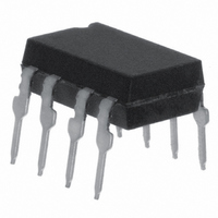
OPTOCPLR 10MBD 2CH 5KV/US 8DIP
Manufacturer
Vishay
Specifications of VO2631
Voltage - Isolation
5300Vrms
Number Of Channels
2, Unidirectional
Current - Output / Channel
50mA
Data Rate
10MBd
Propagation Delay High - Low @ If
50ns @ 7.5mA
Current - Dc Forward (if)
15mA
Input Type
DC
Output Type
Open Collector
Mounting Type
Through Hole
Package / Case
8-DIP (0.300", 7.62mm)
Maximum Fall Time
0.007 us
Minimum Forward Diode Voltage
1.1 V
Output Device
Logic Gate Photo IC
Configuration
2 Channel
Maximum Baud Rate
10 MBps
Maximum Forward Diode Voltage
1.7 V
Maximum Reverse Diode Voltage
5 V
Maximum Power Dissipation
60 mW
Maximum Operating Temperature
+ 100 C
Minimum Operating Temperature
- 40 C
No. Of Channels
2
Optocoupler Output Type
Logic Gate
Input Current
10mA
Output Voltage
7V
Opto Case Style
DIP
No. Of Pins
8
Propagation Delay Low-high
49ns
Isolation Voltage
5.3kV
Rohs Compliant
Yes
Lead Free Status / RoHS Status
Lead free / RoHS Compliant
Lead Free Status / RoHS Status
Lead free / RoHS Compliant, Lead free / RoHS Compliant
Other names
751-1381-5
VO2631
VO2631
Available stocks
Company
Part Number
Manufacturer
Quantity
Price


6N137, VO2601, VO2611, VO2630, VO2631, VO4661
Vishay Semiconductors
Notes
• Stresses in excess of the absolute maximum ratings can cause permanent damage to the device. Functional operation of the device is not
(1)
www.vishay.com
2
THE PRODUCTS DESCRIBED HEREIN AND THIS DOCUMENT ARE SUBJECT TO SPECIFIC DISCLAIMERS, SET FORTH AT
TRUTH TABLE (positive logic)
LED
On
Off
On
Off
On
Off
ABSOLUTE MAXIMUM RATINGS
PARAMETER
INPUT
Average forward current (single channel)
Average forward current (per channel for
dual channel)
Reverse input voltage
Enable input voltage
Enable input current
Surge current
Output power dissipation
(single channel)
Output power dissipation (per channel for
dual channel)
OUTPUT
Supply voltage
Output current
Output voltage
Output power dissipation (single channel)
Output power dissipation (per channel for
dual channel)
COUPLER
Isolation test voltage
Storage temperature
Operating temperature
Lead solder temperature
Solder reflow temperature
RECOMMENDED OPERATING CONDITIONS
PARAMETER
Operating temperature
Supply voltage
Input current low level
Input current high level
Logic high enable voltage
Logic low enable voltage
Output pull up resistor
Fanout
implied at these or any other conditions in excess of those given in the operational sections of this document. Exposure to absolute
maximum ratings for extended periods of the time can adversely affect reliability.
Refer to reflow profile for soldering conditions for surface mounted devices (SMD). Refer to wave profile for soldering conditions for through
hole devices (DIP).
(1)
For technical questions, contact:
TEST CONDITION
High Speed Optocoupler, Single and Dual,
R
L
This document is subject to change without notice.
(1)
= 1 k
TEST CONDITION
1 min maximum
(T
amb
t = 100 μs
for 10 s
t = 1 s
= 25 °C, unless otherwise specified)
ENABLE
NC
NC
H
H
L
L
SYMBOL
optocoupleranswers@vishay.com
10 MBd
T
V
V
V
I
I
R
amb
FH
N
FL
CC
EH
EL
L
SYMBOL
P
P
P
P
T
I
V
V
T
FSM
V
V
V
amb
I
I
diss
diss
I
diss
diss
I
ISO
CC
stg
O
F
F
E
R
O
E
MIN.
- 40
330
4.5
0
5
2
0
- 55 to + 150
- 40 to + 100
V
CC
VALUE
5300
200
260
260
20
15
+ 0.5 V
35
25
50
85
60
5
5
7
7
MAX.
100
V
250
5.5
0.8
4K
15
CC
5
OUTPUT
www.vishay.com/doc?91000
Document Number: 84732
H
H
H
H
L
L
Rev. 1.5, 08-Apr-11
UNIT
V
mW
mW
mW
mW
mA
mA
mA
mA
mA
UNIT
°C
°C
°C
°C
RMS
V
V
V
V
mA
°C
μA
V
V
V
-
Related parts for VO2631
Image
Part Number
Description
Manufacturer
Datasheet
Request
R

Part Number:
Description:
357-036-542-201 CARDEDGE 36POS DL .156 BLK LOPRO
Manufacturer:
Vishay
Datasheet:
Part Number:
Description:
357-036-542-201 CARDEDGE 36POS DL .156 BLK LOPRO
Manufacturer:
Vishay
Datasheet:
Part Number:
Description:
357-036-542-201 CARDEDGE 36POS DL .156 BLK LOPRO
Manufacturer:
Vishay
Datasheet:
Part Number:
Description:
357-036-542-201 CARDEDGE 36POS DL .156 BLK LOPRO
Manufacturer:
Vishay
Datasheet:
Part Number:
Description:
357-036-542-201 CARDEDGE 36POS DL .156 BLK LOPRO
Manufacturer:
Vishay
Datasheet:
Part Number:
Description:
357-036-542-201 CARDEDGE 36POS DL .156 BLK LOPRO
Manufacturer:
Vishay
Datasheet:
Part Number:
Description:
357-036-542-201 CARDEDGE 36POS DL .156 BLK LOPRO
Manufacturer:
Vishay
Datasheet:
Part Number:
Description:
357-036-542-201 CARDEDGE 36POS DL .156 BLK LOPRO
Manufacturer:
Vishay
Datasheet:
Part Number:
Description:
357-036-542-201 CARDEDGE 36POS DL .156 BLK LOPRO
Manufacturer:
Vishay
Datasheet:
Part Number:
Description:
357-036-542-201 CARDEDGE 36POS DL .156 BLK LOPRO
Manufacturer:
Vishay
Datasheet:
Part Number:
Description:
357-036-542-201 CARDEDGE 36POS DL .156 BLK LOPRO
Manufacturer:
Vishay
Datasheet:
Part Number:
Description:
357-036-542-201 CARDEDGE 36POS DL .156 BLK LOPRO
Manufacturer:
Vishay
Datasheet:
Part Number:
Description:
357-036-542-201 CARDEDGE 36POS DL .156 BLK LOPRO
Manufacturer:
Vishay
Datasheet:
Part Number:
Description:
357-036-542-201 CARDEDGE 36POS DL .156 BLK LOPRO
Manufacturer:
Vishay
Datasheet:
Part Number:
Description:
357-036-542-201 CARDEDGE 36POS DL .156 BLK LOPRO
Manufacturer:
Vishay
Datasheet: