NM485DC Murata Power Solutions Inc, NM485DC Datasheet
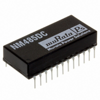
ISOLATED INTERFACE EIA-485 DL

NM485DC

Manufacturer Part Number
NM485DC
Description
ISOLATED INTERFACE EIA-485 DL
Manufacturer
Murata Power Solutions Inc
Datasheet

Specifications of NM485DC

Data Rate
1.25Mbps
Package / Case
24-DIP (0.667", 16.95mm)
Inputs - Side 1/side 2
RS-485
Number Of Channels
4
Isolation Rating
1000Vrms
Voltage - Supply
4.75 V ~ 5.25 V
Propagation Delay
72ns
Output Type
Tri-State
Operating Temperature
0°C ~ 60°C
Supply Voltage Range
4.75V To 5.25V
Logic Case Style
DIP
No. Of Pins
24
Operating Temperature Range
0°C To +60°C
Svhc
No SVHC (18-Jun-2010)
Base
RoHS Compliant
Lead Free Status / RoHS Status
Lead free / RoHS Compliant
Lead Free Status / RoHS Status
Lead free / RoHS Compliant
Other names
811-1445-5

Available stocks

Company
Part Number
Manufacturer
Quantity
Price
Part Number:
NM485DC
Manufacturer:
Murata Power Solutions Inc
Quantity:
135
FEATURES
DESCRIPTION
The NM485DC is an electrically isolated dual
differential driver and receiver designed for bal-
anced mulipoint bus transmission at rates up to
1.25Mbits per second. The device provides two
receive channels and two driver channels. The
two driver channels have an active high enable.
No external components are needed and a single
5V input supply powers all functions either side of
the isolation boundary. The driver outputs provide
limiting for positive and negative currents and
thermal shutdown protection from line fault condi-
tions on the transmission bus line. The receiver
outputs will always be high if the receiver inputs
are open. The isolation voltage between input and
output is 1000Vrms, the devices are supplied in a
low profi le 24 pin DIL plastic package.
www.murata-ps.com
www.murata-ps.com
RoHS compliant
Single 5V supply
Thermal shutdown protection
EIA-485 and CCITT V.28 compatible
Dual differential driver and receiver
Driver tri-state outputs active high enable
Low Profi le 24 pin DIL package style
1kVrms Isolation
www.murata-ps.com/rohs
For full details go to
 
All data taken at T
ELECTRICAL CHARACTERISTICS
Parameter
Supply voltage, V
High level input voltage, V
Low level input voltage, V
Common mode output voltage, V
High level output current I
Low level output current, I
Common mode input voltage, V
Differential input voltage, V
High level output current, I
Low level output current, I
EACH RECEIVER ELECTRICAL CHARACTERISTICS
Parameter
High threshold differential input, V
Low threshold differential input, V
Input hysteresis, ΔV
High level output voltage, V
Low level output voltage, V
Line input current, I
Short circuit output current, I
Input resistance, R
RECEIVER SWITCHING CHARACTERISTICS
Parameter
Propagation delay time L to H, T
Propagation delay time H to L, T
RECEIVER FUNCTION TABLE
ISOLATION CHARACTERISTICS
Parameter
Isolation test voltage
ABSOLUTE MAXIMUM RATINGS
Supply voltage V
Input voltage D
Input voltage range, receiver A or B inputs
Receiver differential input voltage range
Output voltage range, driver
Power dissipation
Isolation capacitance
Isolation voltage (fl ash tested for 1 second)
Data transmission rate
Lead temperature 1.5mm from case for 10 seconds
A
X
=25°C, V
CC
ENABLE and D inputs
CC
Differential inputs A-B
I
with respect to pin 11
I
T
-0.2V<V
CC
V
=5V.
V
IL
ID
OH
OL
OL
ID
IH
OH
ID
OL
≤-0.2V
OH
≥0.2V
ID
OS
<+0.2V
IC
PLH
PHL
OC
TL
TH
Technical enquiries email: mk@murata-ps.com, tel: +44 (0)1908 615232
Test conditions
D
Driver
Receiver
Test conditions
V
V
V
V
Other input at 0V, V
Test conditions
V
Conditions
Flash tested for 1 second
O
O
ID
ID
ID
X
=2.7V, I
=0.5V, I
=200mV, I
=200mV, I
=-1.5V to 1.5V, C
ENABLE and D inputs
Isolated Dual EIA-485 Driver and Receiver
O
O
=-0.4mA
=16mA
OH
OL
=-5.0mA
=25mA
I
I
=12V
=-12V
L
=15pF
NM485DC Series
2009-12-09 KII_NM485DC.A03 Page 1 of 7
1000
Min.
4.75
Min.
Min.
Min.
-7.0
-0.2
2.8
2.7
12
Undefi ned
High level
Low level
RX
OUT
Typ.
Typ.
Typ.
Typ.
5.0
-25V to +25V
-25V to +25V
-10V to +15V
50
70
72
1000Vrms
1.25Mbps
2000mW
300ºC
40pF
7V
7V
Max.
Max.
Max.
Max.
5.25
±12
±12
-5.0
-0.8
155
135
-60
-15
0.8
0.2
0.8
1.0
12
60
25
Units
Units
Units
Units
Vrms
mA
mA
mA
mA
mV
mA
mA
mA
ns
ns
V
V
V
V
V
V
V
V
V
V

Related parts for NM485DC

NM485DC Summary of contents

Page 1

... Driver tri-state outputs active high enable Low Profi pin DIL package style 1kVrms Isolation DESCRIPTION The NM485DC is an electrically isolated dual differential driver and receiver designed for bal- anced mulipoint bus transmission at rates up to 1.25Mbits per second. The device provides two receive channels and two driver channels ...

Page 2

... Min. Typ 150 Output Z Low level High level High impedance Min. Typ. 0 -40 Technical enquiries email: mk@murata-ps.com, tel: +44 (0)1908 615232 2009-12-09 KII_NM485DC.A03 Page Max. Units 5.0 V ±0.2 V 3.0 V ±0.2 V ±100 μA 20 μA -15 mA -250 mA 250 mA Max ...

Page 3

... The maximum number of drivers and receivers that may be placed on a single communication bus depends upon their loading characteristics, relative to the defi nition of a Unit Load (U.L.), transmission speed does not affect the unit load capability. As the NM485DC complies with the EIA-485 standard a maximum of 32 unit loads per line is recommended. A unit load usually consists of a driver-receiver pair, but not the line termination resistors. With only a 5V supply connected, the NM485DC receiver and differential outputs give levels greater than +2.7V and ± ...

Page 4

... However the added parasitic capacitance will load down the bus, and should therefore be taken into consideration. Figure 4 Figure 6 www.murata-ps.com Isolated Dual EIA-485 Driver and Receiver Figure 5 Technical enquiries email: mk@murata-ps.com, tel: +44 (0)1908 615232 NM485DC Series 2009-12-09 KII_NM485DC.A03 Page ...

Page 5

... A question commonly asked is, “What is the continuous voltage that can be applied across the part in normal operation?” For a part holding no specifi c agency approvals, such as the NM485DC series, both input and output should normally be maintained within SELV limits i.e. less than 42.4V peak, or 60VDC. The isolation test voltage represents a measure of immunity to transient voltages and the part should never be used as an element of a safety isolation system. The part could be expected to function correctly with several hundred volts offset applied continuously across the isolation barrier ...

Page 6

... Isolated Dual EIA-485 Driver and Receiver 0.012 (0.30) 0.008 (0.20) 0.6673 (16.95) MAX RECOMMENDED FOOTPRINT All dimensions are in inches (mm) ±0.01 (0.25) TUBE OUTLINE DIMENSIONS All dimensions are in inches (mm) ±0.01 (0.25) Technical enquiries email: mk@murata-ps.com, tel: +44 (0)1908 615232 2009-12-09 KII_NM485DC.A03 Page Tube Quantity : 15 ...

Page 7

... The descriptions contained herein do not imply the granting of licenses to make, use, or sell equipment constructed in accordance therewith. Specifi cations are subject to change without notice. Technical enquiries email: mk@murata-ps.com, tel: +44 (0)1908 615232 2009-12-09 KII_NM485DC.A03 Page © 2009 Murata Power Solutions, Inc. ...

Related keywords