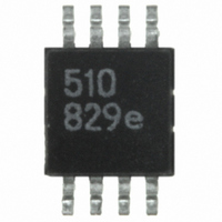
IL510-1E NVE, IL510-1E Datasheet

IL510-1E
Specifications of IL510-1E
Related parts for IL510-1E
IL510-1E Summary of contents
Page 1
... IL516 IsoLoop is a registered trademark of NVE Corporation. *U.S. Patent numbers 5,831,426; 6,300,617 and others. NVE Corporation 11409 Valley View Road, Eden Prairie, MN 55344-3617 IL510/IL511/IL514/IL515/IL516 Low-Cost Digital Isolators Features +3.3 V CMOS/TTL Compatible 2 Mbps Maximum Speed −40ºC to 85ºC Operating Temperature ...
Page 2
... Safety and Approvals IEC61010-1 TUV Certificate Numbers: N1502812, N1502812-101 Classification as Reinforced Insulation Model IL5xx-1 IL5xx-3 IL5xx UL 1577 Component Recognition Program File Number: E207481 Rated 2500V for 1 minute RMS Soldering Profile Per JEDEC J-STD-020C, MSL=2 IL510/IL511/IL514/IL515/IL516 Symbol Min. Typ. − − −0 − ...
Page 3
... IL510 Pin Connections 1 V Supply voltage DD1 2 IN Data in Internal refresh clock disable 3 SYNC (normally enabled and internally held low with 10 kΩ) 4 GND Ground return for V 1 DD1 5 GND Ground return for V 2 DD2 6 OUT Data out Output enable (internally held low with 100 kΩ) ...
Page 4
... DD 9 GND Ground return for connection 11 IN Data in, channel Data in, channel OUT Data out, channel OUT Data out, channel GND Ground return for Supply voltage DD2 IL510/IL511/IL514/IL515/IL516 V DD1 GND SYNC GND 1 IL515 V DD1 GND OUT 3 OUT 4 NC GND 1 IL516 4 V DD2 ...
Page 5
... Timing Diagrams Truth Tables Output Enable IL510/IL511/IL514/IL515/IL516 Legend t Propagation Delay, Low to High PLH t Propagation Delay, High to Low PHL t Minimum Pulse Width PW t Propagation Delay, Low to High Impedance PLZ t Propagation Delay, High Impedance to High PZH t Propagation Delay, High to High Impedance PHZ t Propagation Delay, High Impedance to Low ...
Page 6
... Volt Electrical Specifications Electrical specifications are unless otherwise stated. min max Parameters Input Quiescent Supply Current IL510, IL511, IL515 IL514 IL516 Output Quiescent Supply Current IL510 IL511, IL514, IL516 IL515 Logic Input Current Logic High Output Voltage Logic Low Output Voltage ...
Page 7
... Volt Electrical Specifications Electrical specifications are unless otherwise stated. min max Parameters Input Quiescent Supply Current IL510, IL511, IL515 IL514 IL516 Output Quiescent Supply Current IL510 IL511, IL514, IL516 IL515 Logic Input Current Logic High Output Voltage Logic Low Output Voltage ...
Page 8
... If internal clock is used, devices will respond to DC states on inputs within a maximum of 9 µs. Outputs may oscillate if the SYNC input slew rate is less than 1 V/ms. 11 the maximum time for the internal refresh clock to shut down. off IL510/IL511/IL514/IL515/IL516 and/or t between devices at 25°C. PHL PLH < ...
Page 9
... IsoLoop Isolators’ Wheatstone bridge configuration and differential magnetic field signaling ensure excellent EMC performance against all relevant standards. Additionally, on the IL510 and IL515, the internal clock can be disabled for even better EMC performance. These isolators are fully compliant with generic EMC standards EN50081, EN50082-1 and the umbrella line-voltage standard for Information Technology Equipment (ITE) EN61000 ...
Page 10
... Illustrative Applications Isolated A/D Converter Bridge Bias Clock Generator A delta-sigma A-D converter interfaced with the three-channel IL514. Multiple channels can easily be combined using the IL514’s output enable function. IL510/IL511/IL514/IL515/IL516 Delta Sigma A/D CS5532 Bridge + Bridge - Iso SD Out Iso CS Iso SCK ...
Page 11
... Vdc S G Microcontroller A typical primary-side controller uses the IL511 to drive the synchronous rectification signals from primary side to secondary side. IL511 pulse- width distortion minimizes MOSFET dead time and maximizes efficiency. The ultra-small MSOP package minimizes board area. IL510/IL511/IL514/IL515/IL516 SYNC OE Latch SYNC OE ...
Page 12
... SOIC Package 0.189 (4.8) 0.197 (5.0) 0.228 (5.8) 0.150 (3.8) 0.244 (6.2) 0.157 (4. 0.013 (0.33) 0.020 (0.50) IL510/IL511/IL514/IL515/IL516 0˚ 6˚ 0.016 (0.40) 0.027 (0.70) 0.032 (0.80) 0.043 (1.10) 0.002 (0.05) 0.006 (0.15) 0.028 (0.70) 0.024 (0.60) NOTE: Pin spacing is a BASIC 0.005 (0.13) dimension ...
Page 13
... SOIC Package 0.397 (10.1) 0.413 (10.5) Pin 1 identified by either an indent or a marked dot 0.394 (10.00) 0.419 (10.64) IL510/IL511/IL514/IL515/IL516 Dimensions in inches (mm) 0.152 (3.86) 0.157 (3.99) 0.013 (0.3) 0.020 (0.5) 0.007 (0.2) 0.016 (0.4) 0.013 (0.3) 0.050 (1.3) ...
Page 14
... Ordering Information TR13 IL510/IL511/IL514/IL515/IL516 Bulk Packaging Blank = Tube TR7 = 7'' Tape and Reel TR13 = 13'' Tape and Reel Package Blank = 80/20 Tin/Lead Plating E = RoHS Compliant Package Type -1 = 8-pin MSOP -3 = 0.15'' 8-pin or 16-pin SOIC (not available for IL515) Blank = 0.30'' 16-pin SOIC Channels Drive Channel Drive Channels Drive Channels ...
Page 15
... Initial release July 2008 ISB-DS-001-IL500-A Preliminary release June 2008 IL510/IL511/IL514/IL515/IL516 Clarified SYNC function. Changed pin spacing specification on MSOP drawing. Added EMC details. Add Output Enable to IL515. IEC 61010-2001 Approval (removed “pending”). ...
Page 16
... NVE Corporation. NVE Corporation does not authorize, nor warrant, any NVE Corporation product for use in life support devices or systems or other critical applications without the express written approval of the President of NVE Corporation. Specifications shown are subject to change without notice. ISB-DS-001-IL500-G November 2010 IL510/IL511/IL514/IL515/IL516 16 ...


