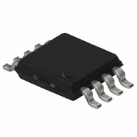
IL610-1E NVE, IL610-1E Datasheet

IL610-1E
Specifications of IL610-1E
Related parts for IL610-1E
IL610-1E Summary of contents
Page 1
... Features • 100 Mbps Data Rate • Single-ended or Differential Input Operation • Very Wide Input Voltage Range • Failsafe Output (logic high output for zero coil current) • Output Enable (IL610) • 3 Operation / Level Translation • 2500 V Isolation (1 minute) RMS • Low Power Dissipation • ...
Page 2
... Safety Approvals IEC61010-2001 TUV Certificate Numbers: Classification: Reinforced Insulation Model IL610-2E, IL611-2E, IL612-2E IL613E, IL614E IL610-3E, IL611-3E, IL612-3E, IL613-3E, IL614-3E UL 1577 Component Recognition program File #: E207481 Rated 2500V for 1 minute (SOIC, PDIP), 1000V RMS Electrostatic Discharge Sensitivity This product has been tested for electrostatic sensitivity to the limits stated in the specifications. However, NVE recommends that all integrated circuits be handled with appropriate care to avoid damage ...
Page 3
... IL610 Pin Connections internal connection 2 IN+ Coil connection 3 IN- Coil connection internal connection 5 GND Ground return for OUT Data out 7 V Output enable. Internally held low with OE 100 kΩ Supply Voltage DD IL611 Pin Connections Channel 1 coil connection Channel 1 coil connection Channel 2 coil connection ...
Page 4
IL614 Pin Connections 1 V Supply Voltage 1 DD1 2 GND Ground return for V 1 DD1 connected to pin 8) 3 OUT Data out, channel Channel 1 data output enable. Internally RE held low with 100 ...
Page 5
... PWD is defined PHL - PLH equal to the magnitude of the worst case difference in t PSK Symbol Min. Typ. Z 47||8 55||9 COIL TC R 0.16 COIL I 0.5 1 INH I 5 3.5 INL IL610 IL611 IL612 DD1 IL612 DD2 IL613 IL614 DD1 IL614 DD2 V 4 4.0 4.8 ...
Page 6
... The Minimum Pulse Width is the shortest pulse width at which the specified PWD is guaranteed. 5. PWD is defined PHL - PLH equal to the magnitude of the worst case difference in t PSK Symbol Min. Typ. IL610, I 1.3 DD IL611, I 2.6 DD IL612, I 1.3 DD1 IL612, I 1.3 DD2 IL613 IL614 ...
Page 7
... These circuits show the configurations used to obtain the specifications on the previous pages. All applications should follow these circuits closely. The circuits shown use the IL610. However, the input configuration applies to all the devices in the IL600 series. A bypass capacitor should be placed across the current limit resistor to achieve the enhanced timing specifications. This capacitor must be in all 3 ...
Page 8
... The absolute maximum current through the coil of the IL600 series DC. The worst case logic threshold current is 5 mA. While typical threshold currents are actually less than this, NVE recommends designing logic threshold current in each application. In all cases, the current must flow from In- to In+ in the coil to switch the output low. This is the case for true or inverted data, or single ended or differential configurations ...
Page 9
... DD Applications Information The IL600 series devices are current mode isolators. This means that a current of a certain magnitude and direction must flow in the input coil to change the output logic state. Figure 3 shows a simplified transfer curve for a typical IL600 series data channel. Bridge o/p (mV) ...
Page 10
... GMR bridge output through the comparator threshold voltage with reduced propagation delay and improved pulse width distortion. Figure 5 shows how the capacitor is connected in the case of the IL610. Note that the capacitor can be used in both inverting and non-inverting modes of operation. The use of the capacitor gives a great deal of design headroom and can usually eliminate design concerns related to temperature range and power supply fluctuation ...
Page 11
... This reduces cost and complexity. One of the more common applications is an isolated Differential Line Receiver. RS485 and RS422 signals can be terminated on the IL610 at a fraction of the cost of an isolated RS485 node. Magnetic Field Immunity All IsoLoop devices operate by imposing a ...
Page 12
Two main options for enhancing external magnetic field immunity are shown below. 1. Orientation of the device with respect to the field direction An applied field in the direction of “H1” with respect to the orientation of the device will ...
Page 13
Application Diagrams Note: In all applications 3 SJA1000 SJA1000 SS1 SS1 DD3 DD3 13 13 TX0 TX0 14 14 TX1 TX1 1K ...
Page 14
Note: In all applications 3 DD1 DD1 ...
Page 15
... Note: In all applications 3 IL610 IL610 Hi-Drive Hi-Drive + + IL610 IL610 Lo-Drive Lo-Drive + + GND GND 1 1 Single Phase Power Control must be used. (See Test Circuit #1) Boost 10-20 V 10- LM309H LM309H IR2102 IR2102 HIN HIN LIN LIN COM COM 5 5 GND GND Note. Capacitors C Note ...
Page 16
Note: In all applications 3 RTS RTS CTS CTS 3 ...
Page 17
Package Drawings, Dimensions and Specifications 8-pin MSOP Package 8-pin SOIC Package 8-pin PDIP Package IL600 Series 17 ...
Page 18
SOIC 0.3" 16-pin SOIC IL600 Series 18 ...
Page 19
Ordering Information and Valid Part Numbers IL600 Series 19 ...
Page 20
Revision History ISB-DS-001-IL600-F Changes ISB-DS-001-IL600-E Changes 7. 8. ISB-DS-001-IL600-D Changes 9. 10. 11. Data rate increased to 100 Mbps Boost Capacitor information added for 5 V and 3.3 V applications. Input threshold for logic ...
Page 21
... Magnetic Field Sensors, Magnetic Field Gradient Sensors (Gradiometer), Digital Magnetic Field Sensors, Digital Signal Isolators and Isolated Bus Transceivers. NVE is a leader in GMR research and in 1994 introduced the world’s first products using GMR material, a line of GMR magnetic field sensors that can be used for position, magnetic media, wheel speed and current sensing. ...


