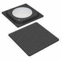
DS34T108GN+ Maxim Integrated Products, DS34T108GN+ Datasheet - Page 4

DS34T108GN+
Manufacturer Part Number
DS34T108GN+
Description
IC TDM OVER PACKET 484HSBGA
Manufacturer
Maxim Integrated Products
Type
TDM (Time Division Multiplexing)r
Datasheet
1.DS34T108GN.pdf
(16 pages)
Specifications of DS34T108GN+
Applications
Data Transport
Mounting Type
Surface Mount
Package / Case
484-BGA Exposed Pad, 484-eBGA, 484-HBGA
Lead Free Status / RoHS Status
Lead free / RoHS Compliant
ABRIDGED DATA SHEET
____________________________________________________ DS34T101, DS34T102, DS34T104, DS34T108
The CESoPSN payload-type machine maps and demaps structured E1, T1, E3 or T3 data flows into and out of IP,
MPLS or Ethernet packets with static assignment of timeslots inside a bundle according to ITU-T Y.1413, Y.1453,
MEF 8, MFA 8.0.0 and the IETF RFC 5086 (CESoPSN). It supports E1/T1/E3/T3 while taking into account the
TDM structure. The level of structure must be chosen for proper payload conversion such as the framing type (i.e.
frame or multiframe). This method is less sensitive to PSN impairments but lost packets could still cause service
interruption.
E1/T1 Transceivers
The LIU in each transceiver is composed of a transmitter, a receiver and a jitter attenuator. Internal software
configurable impedance matching is provided for both transmit and receive paths, reducing external component
count. The transmit interface is responsible for generating the necessary waveshapes for driving the E1/T1 twisted
pair or coax cable and providing the correct source impedance depending on the type of cable used. T1 waveform
generation includes DSX–1 line build-outs as well as CSU line build-outs of 0dB, -7.5dB, -15dB, and -22.5dB. E1
waveform generation includes G.703 waveshapes for both 75 coax and 120 twisted cables. The receive
interface provides the correct line termination and recovers clock and data from the incoming line. The receive
sensitivity adjusts automatically to the incoming signal level and can be programmed for 0dB to -43dB or 0dB to
-12dB for E1 applications and 0dB to -15dB or 0dB to -36dB for T1 applications. The jitter attenuator removes
phase jitter from the transmitted or received signal. The crystal-less jitter attenuator can be placed in either the
transmit or receive path and requires only a T1- or E1-rate reference clock, which is typically synthesized by the
CLAD1 block from a common reference frequency of 10MHz, 19.44MHz, 38.88MHz or 77.76MHz.
In the framer block, the transmit formatter takes data from the TDMoP core, inserts the appropriate framing
patterns and alarm information, calculates and inserts CRC codes, and provides the HDB3 or B8ZS encoding (zero
code suppression) and AMI line coding. The receive framer decodes AMI, HDB3 and B8ZS line coding, finds frame
and multiframe alignment in the incoming data stream, reports alarm information, counts framing/coding/CRC
errors, and provides clock, data, and frame-sync signals to the TDMoP core.
Both transmit and receive paths have built-in HDLC controller and BERT blocks. The HDLC blocks can be
assigned to any timeslot, a portion of a timeslot or to the FDL (T1) or Sa bits (E1). Each controller has 64-byte
FIFOs, reducing the amount of processor overhead required to manage the flow of data. The BERT blocks can
generate and synchronize with pseudo-random and repetitive patterns, insert errors (singly or at a constant error
rate) and detect and count errors to calculate bit error rates.
4 of 16


