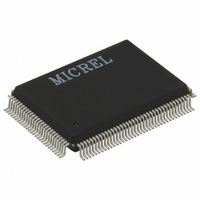
KSZ8993 Micrel Inc, KSZ8993 Datasheet - Page 16

KSZ8993
Manufacturer Part Number
KSZ8993
Description
IC SWITCH 10/100 3PORT 128PQFP
Manufacturer
Micrel Inc
Specifications of KSZ8993
Applications
*
Mounting Type
Surface Mount
Package / Case
128-MQFP, 128-PQFP
Number Of Primary Switch Ports
3
Internal Memory Buffer Size
64
Operating Supply Voltage (typ)
2.5/3.3V
Fiber Support
Yes
Integrated Led Drivers
Yes
Phy/transceiver Interface
MII/SNI
Power Supply Type
Analog/Digital
Package Type
PQFP
Data Rate (typ)
10/100Mbps
Vlan Support
Yes
Operating Temperature (max)
70C
Operating Temperature (min)
0C
Pin Count
128
Mounting
Surface Mount
Jtag Support
No
Operating Supply Voltage (max)
2.75/3.6V
Operating Supply Voltage (min)
2.35V
Operating Temperature Classification
Commercial
Lead Free Status / RoHS Status
Lead free / RoHS Compliant
Other names
576-1032
Available stocks
Company
Part Number
Manufacturer
Quantity
Price
Company:
Part Number:
KSZ8993
Manufacturer:
MICREL
Quantity:
4 000
Part Number:
KSZ8993
Manufacturer:
MICREL/麦瑞
Quantity:
20 000
Company:
Part Number:
KSZ8993F
Manufacturer:
Micrel Inc
Quantity:
135
Company:
Part Number:
KSZ8993F
Manufacturer:
MICREL22
Quantity:
386
Company:
Part Number:
KSZ8993FL
Manufacturer:
Micrel Inc
Quantity:
135
Part Number:
KSZ8993FL
Manufacturer:
MICREL/麦瑞
Quantity:
20 000
Part Number:
KSZ8993M
Manufacturer:
MICREL/麦瑞
Quantity:
20 000
Part Number:
KSZ8993MI
Manufacturer:
KENDIN
Quantity:
20 000
KS8993
Micrel
Functional Overview: Physical Layer Transceiver
100BaseTX Transmit
The 100BaseTX transmit function performs parallel to serial conversion, 4B/5B coding, scrambling, NRZ to NRZI conversion,
MLT3 encoding and transmission. The circuit starts with a parallel to serial conversion, which converts the data from the MAC
into a 125MHz serial bit stream. The data and control stream is then converted into 4B/5B coding followed by a scrambler. The
serialized data is further converted from NRZ to NRZI format, then transmitted in MLT3 current output. The output current is
set by an external 1% 3.01k resistor for the 1:1 transformer ratio. It has a typical rise/fall time of 4ns and complies to the ANSI
TP-PMD standard regarding amplitude balance, overshoot and timing jitters.
100BaseTX Receive
The 100BaseTX receiver function performs adaptive equalization, DC restoration, MLT3 to NRZI conversion, data and clock
recovery, NRZI to NRZ conversion, de-scrambling, 4B/5B decoding and serial to parallel conversion. The receiving side starts
with the equalization filter to compensate inter-symbol interference (ISI) over the twisted pair cable. Since the amplitude loss
and phase distortion is a function of the length of the cable, the equalizer has to adjust its characteristics to optimize the
performance. In this design, the variable equalizer will make an initial estimation based on comparisons of incoming signal
strength against some known cable characteristics, then tunes itself for optimization. This is an ongoing process and can self
adjust against the environmental changes such as temperature variations.
The equalized signal then goes through a DC restoration and data conversion block. The DC restoration circuit is used to
compensate for the effect of base line wander and improve the dynamic range. The differential data conversion circuit converts
the MLT3 format back to NRZI. The slicing threshold is also adaptive.
The clock recovery circuit extracts the 125MHz clock from the edges of the NRZI signal. This recovered clock is then used to
convert the NRZI signal into the NRZ format. The signal is then sent through the de-scrambler followed by the 4B/5B decoder.
Finally, the NRZ serial data is provided as the input data to the MAC.
PLL Clock Synthesizer
The KS8993 generates clocks for the external MII and SNI interface based on the interface type selected.
Scrambler/De-scrambler (100BaseTX only)
The purpose of the scrambler is to spread the power spectrum of the signal in order to reduce EMI and baseline wander. The
data is scrambled by the use of an 11-bit wide linear feedback shift register (LFSR). This can generate a 2047-bit non-repetitive
sequence. The receiver will then de-scramble the incoming data stream with the same sequence at the transmitter.
100BaseFX Operation
100BaseFX operation is very similar to 100BaseTX operation with the differences being that the scrambler/de-scrambler and
MLT3 encoder/decoder are bypassed on transmission and reception. In this mode the auto-negotiation feature is bypassed
since there is no standard that supports fiber auto-negotiation.
100BaseFX Signal Detection
The physical port runs in 100BaseFX mode if FXSDx >.6V. This signal is referenced to VREFx which is set at 1/2 Vdd but can
be overridden by an external level. VREFx can be connected to the “minus” signal of a differential pair coming from the fiber
module (“plus connects to FXSDx) used to convey signal detect. When FXSDx is below .6V then 100BaseFX mode is disabled.
100BaseFX Far End Fault
Far end fault occurs when the signal detection is logically false from the receive fiber module. When this occurs, the
transmission side signals the other end of the link by sending 84 1’s followed by a zero in the idle period between frames.
“I/O Description”
Far End Fault can be disabled by setting external hardware pin TEST[2]=0 and TEST[1] = float. See
for pin
description.
10BaseT Transmit
The output 10BaseT driver is incorporated into the 100BaseT driver to allow transmission with the same magnetic. They are
internally wave-shaped and pre-emphasized into outputs with a typical 2.2V amplitude. The harmonic contents are at least
27dB below the fundamental when driven by an all-ones Manchester-encoded signal.
Special note for 10BaseT operation: With an operating voltage of 2.5V, the KS8993 does not always achieve the specified
transmit voltage swing greater than or equal to 2.2V as specified by IEEE 802.3. The important factor however is that the
KS8993 does adhere to the specified receive signal voltages using the IEEE twisted pair model with a 100 load. The transmit
voltage swing can be increased to 2.2V or above by increasing the supply voltage to 2.65V if so desired.
10BaseT Receive
On the receive side, input buffer and level detecting squelch circuits are employed. A differential input receiver circuit and a
PLL perform the decoding function. The Manchester-encoded data stream is separated into clock signal and NRZ data. A
KS8993
16
May 2005


