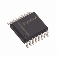
MAX738ACWE Maxim Integrated Products, MAX738ACWE Datasheet

MAX738ACWE
Specifications of MAX738ACWE
Available stocks
Related parts for MAX738ACWE
MAX738ACWE Summary of contents
Page 1
... MAX744A ON/OFF SHDN OUT REF CC SS GND ________________________________________________________________ Maxim Integrated Products For free samples & the latest literature: http://www.maxim-ic.com, or phone 1-800-998-8800 ________________________________Features 750mA Load Currents (MAX738A/MAX744A) High-Frequency, Current-Mode PWM 159kHz to 212.5kHz Guaranteed Oscillator Frequency Limits (MAX744A) 85% to 96% Efficiencies 1.7mA Quiescent Current 6µ ...
Page 2
Step-Down, Current-Mode PWM DC-DC Converters ABSOLUTE MAXIMUM RATINGS Pin Voltages V+ (MAX730A) ......................................................+12V, -0.3V V+ (MAX738A/MAX744A) .....................................+18V, -0.3V LX (MAX730A) .................................(V+ - 12V) to (V+ + 0.3V) LX (MAX738A/MAX744A) ................(V+ - 21V) to (V+ + 0.3V) OUT .................................................................................±25V SS, ...
Page 3
Current-Mode PWM DC-DC Converters ELECTRICAL CHARACTERISTICS (continued) (Circuit of Figure for the MAX730A 12V for the MAX738A/MAX744A, I unless otherwise noted.) PARAMETER CONDITIONS I = 0mA to 300mA LOAD Load Regulation I = 0mA ...
Page 4
Step-Down, Current-Mode PWM DC-DC Converters __________________________________________Typical Operating Characteristics (Circuit of Figure +25°C, unless otherwise noted.) A MAX730A EFFICIENCY vs. OUTPUT CURRENT 100 (NOTES 5. ...
Page 5
Current-Mode PWM DC-DC Converters ____________________________Typical Operating Characteristics (continued) (Circuit of Figure +25°C, unless otherwise noted.) A OSCILLATOR FREQUENCY vs. SUPPLY VOLTAGE 220 210 MAX730A 200 190 180 170 160 MAX738A 150 SUPPLY VOLTAGE ...
Page 6
Step-Down, Current-Mode PWM DC-DC Converters ____________________________Typical Operating Characteristics (continued) (Circuit of Figure +25°C, unless otherwise noted.) A MAX738A/MAX744A SWITCHING WAVEFORMS, CONTINUOUS CONDITION 2 s/div A: SWITCH VOLTAGE (LX PIN), 5V/div +12V B: INDUCTOR CURRENT, ...
Page 7
Current-Mode PWM DC-DC Converters ____________________________Typical Operating Characteristics (continued) (Circuit of Figure +25°C, unless otherwise noted.) A MAX730A LOAD-TRANSIENT RESPONSE 50ms/div A: V OUT , 50mV/div, DC-COUPLED B: I OUT , 200mA/div, 20mA TO 300mA ...
Page 8
Step-Down, Current-Mode PWM DC-DC Converters _________________Detailed Description The MAX730A/MAX738A/MAX744A switch-mode regu- lators use a current-mode pulse-width-modulation (PWM) control system coupled with a simple step-down (buck) regulator topography. They convert an unregu- lated DC voltage from 5.2V to 11V for ...
Page 9
Current-Mode PWM DC-DC Converters Table 1. Typical Soft-Start Times MAX730A CIRCUIT CONDITIONS R1 (kΩ) V+ (V) I OUT 510 6 510 9 510 11 510 9 150 510 9 300 510 9 150 510 9 150 None 6 None 9 ...
Page 10
Step-Down, Current-Mode PWM DC-DC Converters SHDN BIAS GEN OUT C5 ERROR AMP 330pF CC 1.23V R1 BANDGAP 510k REF C6 0. ±35 0.1 F GND *SEE TABLE 2 FOR COMPONENT VALUES AND SUPPLIERS Figure 1. ...
Page 11
Current-Mode PWM DC-DC Converters Table 2. Component Values and Suppliers MAX730AC/MAX738AC/MAX744AC Production Commercial Temp. Range Method Inductors L1 = 33µH to 100µH Sumida (708) 956-0666 CD54-101KC (MAX730AC) Surface CD105-101KC Mount (MAX738AC/MAX744AC) Coiltronics (407) 241-7876 CTX100 series L1 = 33µH to ...
Page 12
Step-Down, Current-Mode PWM DC-DC Converters FROM SHDN R1 SS CLAMP 510k SS 1M ±35% C1 1.23V MAX730A MAX738A MAX744A Figure 2. Block Diagram of Soft-Start Circuitry MAX730A +5.2V TO +11.0V MAX738A/MAX744A +6.0V TO +16. ...
Page 13
Current-Mode PWM DC-DC Converters MAX730 EVALUATION KIT Figure 4. DIP PC Layout, Through-Hole Component Placement Diagram (1x scale) Figure 6. DIP PC Layout, Solder Side (1x scale) ______________________________________________________________________________________ 5V, Step-Down, Figure 5. DIP PC Layout, Component Side (1x scale) Figure ...
Page 14
... Wide SO __________________________________________________________Chip Topographies MAX730A SHDN V+ REF SS OUT CC 0.072" (1.828mm) TRANSISTOR COUNT: 274 (MAX730A) 286 (MAX738A/MAX744A); SUBSTRATE CONNECTED TO V+. 14 ______________________________________________________________________________________ __Ordering Information (continued) PART MAX738ACPA MAX738ACWE V+ MAX738AC/D LX MAX738AEPA GND MAX738AEWE OUT MAX738AMJA MAX744ACPA MAX744ACWE MAX744AC/D V+ MAX744AEPA V+ MAX744AEWE LX MAX744AMJA LX *Contact factory for dice specifications. ...
Page 15
Current-Mode PWM DC-DC Converters ________________________________________________________Package Information ______________________________________________________________________________________ 45˚ 0.127mm 0.004in 5V, Step-Down, ...
Page 16
... Maxim cannot assume responsibility for use of any circuitry other than circuitry entirely embodied in a Maxim product. No circuit patent licenses are implied. Maxim reserves the right to change the circuitry and specifications without notice at any time. 16 __________________Maxim Integrated Products, 120 San Gabriel Drive, Sunnyvale, CA 94086 (408) 737-7600 © 1996 Maxim Integrated Products ...


