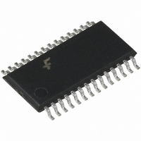
FAN5240MTCX Fairchild Semiconductor, FAN5240MTCX Datasheet

FAN5240MTCX
Specifications of FAN5240MTCX
FAN5240MTCX_NL
FAN5240MTCX_NLTR
FAN5240MTCX_NLTR
Available stocks
Related parts for FAN5240MTCX
FAN5240MTCX Summary of contents
Page 1
... Regulator CORE Ordering Information Part Number FAN5240QSC FAN5240QSCX FAN5240MTC FAN5240MTCX ©2006 Fairchild Semiconductor Corporation FAN5240 Rev. 1.2.0 General Description The FAN5240 is a single output 2-Phase synchronous buck controller to power AMD’s mobile CPU core. The FAN5240 includes a 5-bit digital-to-analog converter (DAC) that adjusts the core PWM output voltage from ...
Page 2
Typical Application VIN (BATTERY 24V VCC + PGOOD FPWM 12 VID0 11 VID1 10 VID2 9 VID3 8 VID4 7 SS C11 20 C10 DELAY 16 R4 ILIM ...
Page 3
Pin Configuration Pin Assignments Pin Pin Number Name 1 LDRV2 Low-Side Drive. The low-side (lower) MOSFET driver output. 27 LDRV1 2 PGND2 Power Ground. The return for the low-side MOSFET driver. 26 PGND1 3 BOOT2 BOOT. The positive supply for ...
Page 4
Pin Assignments (Continued) Pin Pin Number Name 19 PGOOD Power Good Flag. An open-drain output that will pull LOW when the core output below 825mV. PGOOD delays its low to high transition for a time determined by CDELAY when VCORE ...
Page 5
Electrical Specifications ( 6V–24V, and unless otherwise noted.) Parameter Power Supplies V Current CC V Current IN UVLO Threshold Regulator / Control Functions Output voltage Error Amplifier Gain Error Amplifier GBW Error ...
Page 6
Electrical Specifications Parameter PGOOD VCORE Lower Threshold PGOOD Output Delay PGOOD Output Low Leakage Current Note: 1. Guaranteed by slew rate testing VOUT' Soft Start & PGOOD VIN OSC RAMP EA1 ISNS1+ISNS2 5 VCORE+ A1 30µA VCORE- 1K ...
Page 7
Circuit Description Overview The FAN5240 is a 2-phase, single output power man- agement IC, which supplies the low-voltage, high-current power to modern processors for notebook PCs. Using very few external components, the IC controls a preci- sion programmable synchronous buck ...
Page 8
Initialization, Soft Start and PGOOD Assuming EN is high, FAN5240 is initialized when power is applied Should threshold, an internal Power-On Reset function disables the chip. The IC attempts to regulate the VCORE output ...
Page 9
Operation Mode Control The mode-control circuit changes the converter’s mode of operation from PWM to Hysteretic and visa versa, based on the voltage polarity of the SW node when the lower MOSFET is conducting and just before the upper MOSFET ...
Page 10
Current Processing Section The following discussion refers to Figure 6. Setting RSENSE Each phase current is sampled about 200nS after the SW node crosses 0V. For proper converter operation, choose an RSENSE value of MAX R ...
Page 11
Additionally, the CPU power dissipation is also slightly reduced proportional to the applied voltage squared and even slight voltage decrease translates to a measurable reduction in power dissipated. ILOAD Vout (no droop upper lim V ...
Page 12
– REF EAOut Modulator Figure 9. Compensation --------------------- - = 6 kHz --------------------- - ...
Page 13
Since the tolerance on the current limit is largely depen- dent on the ratio of the external resistors it is fairly accu- rate if the voltage drop on the Switching Node side accurate representation of the ...
Page 14
Design and Component Selection Guidelines As an initial step, define operating voltage range and minimum and maximum load currents for the controller. For this discussion, I Max 25A OUT V 5.5V to 21V IN V 0.925V OUT ...
Page 15
High-Side Losses C C ISS G(SW ISS GS GD Figure 12. Switching losses and HDRV ...
Page 16
Layout Considerations Switching converters, even during normal operation, pro- duce short pulses of current which could cause substan- tial ringing and be a source of EMI if layout constrains are not observed. There are two sets of critical components in ...
Page 17
Mechanical Dimensions 28-Pin QSOP Inches Millimeters Symbol Min. Max. Min. 0.053 1.35 A 0.069 A1 0.004 0.10 0.010 A2 - 0.061 B 0.008 0.012 0.20 C 0.007 0.010 0.18 D 0.386 0.394 9.81 E 0.150 0.157 3.81 e 0.025 BSC ...
Page 18
Mechanical Dimensions 28-Pin TSSOP 9.7 0.51 TYP 28 PIN # 1 IDENT 1.2 MAX 0.1 C ALL LEAD TIPS – C – 0.65 0.19–0.30 DIMENSIONS ARE IN MILLIMETERS NOTES: A. Conforms to JEDEC registration MO-153, variation AB, Ref. Note 6, ...
Page 19
... TRADEMARKS The following are registered and unregistered trademarks Fairchild Semiconductor owns or is authorized to use and is not intended exhaustive list of all such trademarks. ACEx™ ® FAST ActiveArray™ FASTr™ Bottomless™ FPS™ Build it Now™ FRFET™ CoolFET™ ...


