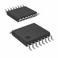
LM5025AMTCX/NOPB National Semiconductor, LM5025AMTCX/NOPB Datasheet - Page 2

LM5025AMTCX/NOPB
Manufacturer Part Number
LM5025AMTCX/NOPB
Description
IC CTLR PWM CLAMP VOLT 16TSSOP
Manufacturer
National Semiconductor
Series
PowerWise®r
Datasheet
1.LM5025ASDNOPB.pdf
(16 pages)
Specifications of LM5025AMTCX/NOPB
Pwm Type
Voltage Mode
Number Of Outputs
2
Frequency - Max
1MHz
Duty Cycle
92.5%
Voltage - Supply
13 V ~ 90 V
Buck
Yes
Boost
Yes
Flyback
Yes
Inverting
Yes
Doubler
No
Divider
No
Cuk
No
Isolated
Yes
Operating Temperature
-40°C ~ 125°C
Package / Case
16-TSSOP
Frequency-max
1MHz
For Use With
LM5025AEVAL - BOARD EVALUATION LM5025ALM5025EVAL - EVALUATION BOARD FOR LM5025
Lead Free Status / RoHS Status
Lead free / RoHS Compliant
Other names
LM5025AMTCX
Available stocks
Company
Part Number
Manufacturer
Quantity
Price
Part Number:
LM5025AMTCX/NOPB
Manufacturer:
TI/德州仪器
Quantity:
20 000
www.national.com
Order Number
LM5025AMTC
LM5025AMTCX
LM5025ASD
LM5025ASDX
Connection Diagram
Ordering Information
Pin Description
Pin
1
2
3
4
5
6
RAMP
Name
TIME
CS1
CS2
REF
V
IN
Source Input Voltage
Modulator ramp signal
Current sense input for cycle-by-cycle limiting If CS1 exceeds 0.5V the outputs will go into Cycle-by-
Current sense input for soft restart
Output overlap/Deadtime control
Precision 5 volt reference output
Package Type
TSSOP-16
TSSOP-16
LLP-16
LLP-16
Description
16-Lead TSSOP, LLP
2
NSC Package Drawing
MTC-16
MTC-16
SDA-16A
SDA-16A
Input to start-up regulator. Input range 13V to 90V, with
transient capability to 105V.
An external RC circuit from Vin sets the ramp slope.
This pin is discharged at the conclusion of every cycle
by an internal FET, initiated by either the internal clock
or the V*Sec Clamp comparator.
Cycle current limit. CS1 is held low for 50ns after
OUT_A switches high providing leading edge blanking.
If CS2 exceeds 0.5V the outputs will be disabled and a
softstart commenced. The soft-start capacitor will be
fully discharged and then released with a pull-up
current of 1µA. After the first output pulse (when SS
=1V), the SS charge current will revert back to 20µA.
An external resistor (R
or dead time for the active clamp output. An R
resistor connected between TIME and GND produces
in-phase OUT_A and OUT_B pulses with overlap. An
R
produces out-of-phase OUT_A and OUT_B pulses with
deadtime.
Maximum output current: 10mA Locally decouple with
a 0.1µF capacitor. Reference stays low until the V
UV comparator is satisfied.
SET
resistor connected between TIME and REF
20107416
Application Information
SET
Supplied As
92 Units per Anti-Static Tube
2500 Units on Tape and Reel
1000 Units on Tape and Reel
4500 Units on Tape and Reel
) sets either the overlap time
SET
CC


