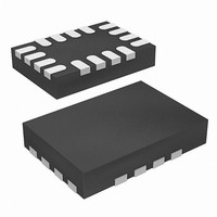
ISL62871HRUZ-T Intersil, ISL62871HRUZ-T Datasheet - Page 14

ISL62871HRUZ-T
Manufacturer Part Number
ISL62871HRUZ-T
Description
IC CTRLR DC/DC PWM 16-TQFN
Manufacturer
Intersil
Datasheet
1.ISL62871HRUZ-T.pdf
(25 pages)
Specifications of ISL62871HRUZ-T
Pwm Type
Controller
Number Of Outputs
1
Frequency - Max
330kHz
Duty Cycle
100%
Voltage - Supply
3.3 V ~ 25 V
Buck
Yes
Boost
No
Flyback
No
Inverting
No
Doubler
No
Divider
No
Cuk
No
Isolated
No
Operating Temperature
-10°C ~ 100°C
Package / Case
16-UTQFN (16-µTQFN)
Frequency-max
330kHz
Lead Free Status / RoHS Status
Lead free / RoHS Compliant
Available stocks
Company
Part Number
Manufacturer
Quantity
Price
Part Number:
ISL62871HRUZ-T
Manufacturer:
INTERSIL
Quantity:
20 000
Where:
Fault Protection
Overcurrent
The overcurrent protection (OCP) setpoint is programmed
with resistor R
and PHASE pins. Resistor R
pin and the actual output voltage of the converter. During
normal operation, the VO pin is a high impedance path,
therefore there is no voltage drop across R
resistor R
R
Figure 10 shows the overcurrent set circuit. The inductor
consists of inductance L and the DC resistance DCR. The
inductor DC current I
which is given by Equation 22:
The I
creating a DC voltage drop across the resistor R
which is given by Equation 23:
The DC voltage difference between the OCSET pin and the
VO pin, which is given by Equation 24:
V
The IC monitors the voltage of the OCSET pin and the VO
pin. When the voltage of the OCSET pin is higher than the
voltage of the VO pin for more than 10µs, an OCP fault
latches the converter off.
V
V
OCSET
OCSET
DCR
ROCSET
- t
- V
- V
- I
- R
FIGURE 10. OVERCURRENT PROGRAMMING CIRCUIT
10µ
from
when V
VS
VS
OCSET
NEW
OLD
T
=
is the sum of the R
–
is the voltage-step delay
is the ±100µA setpoint voltage-step current; positive
PHASE
OCSET
I
L
O
V
=
is the setpoint voltage that V
⋅
VO
is the new setpoint voltage
should always match the value of resistor
VO
NEW
DCR
current source sinks 10µA into the OCSET pin,
10μA R
OCSET
=
V
DCR
> V
⋅
+
+
L
OLD
OCSET
–
V
which is connected across the OCSET
R
creates a voltage drop across DCR,
ROCSET
V
OCSET
DCR
ROCSET
, negative when V
R
SET
O
O
14
_
V
is connected between the VO
DCR
programming resistors
C
=
SEN
I
L
L
⋅
DCR
NEW
–
I
O
L
_
NEW
I
OCSET
. The value of
is changing
OCSET
< V
⋅
V
ISL62871, ISL62872
R
OLD
O
(EQ. 22)
(EQ. 23)
(EQ. 24)
OCSET
C
,
O
Component Selection For R
The value of R
is written as:
Where:
For example, if I
R
Resistor R
to sense the inductor current. To sense the inductor current
correctly not only in DC operation, but also during dynamic
operation, the R-C network time constant R
needs to match the inductor time constant L/DCR. The value
of C
For example, if L is 1.5µH, DCR is 4.5mΩ, and R
9kΩ, the choice of C
When an OCP fault is declared, the PGOOD pin will
pull-down to 35Ω and latch off the converter. The fault will
remain latched until the EN pin has been pulled below the
falling EN threshold voltage V
below the falling POR threshold voltage
Overvoltage
The OVP fault detection circuit triggers after the FB pin
voltage is above the rising overvoltage threshold V
more than 2µs. For example, if the converter is programmed
to regulate 1.0V at the FB pin, that voltage would have to
rise above the typical V
than 2µs in order to trip the OVP fault latch. In numerical terms,
that would be 116% x 1.0V = 1.16V. When an OVP fault is
declared, the PGOOD pin will pull-down to 65Ω and latch-off
the converter. The OVP fault will remain latched until VCC
has decayed below the falling POR threshold voltage
V
pin below the falling EN threshold voltage V
Although the converter has latched-off in response to an
OVP fault, the LGATE gate-driver output will retain the ability
to toggle the low-side MOSFET on and off, in response to
the output voltage transversing the V
thresholds. The LGATE gate-driver will turn-on the low-side
MOSFET to discharge the output voltage, protecting the
load. The LGATE gate-driver will turn-off the low-side
MOSFET once the FB pin voltage is lower than the falling
overvoltage threshold V
falling overvoltage threshold V
C
R
VCC_THF
OCSET
SEN
OCSET
- R
- I
- DCR is the inductor DC resistance
SEN
overcurrent setpoint
OCP fault detection circuit
OC
OCSET
=
is the output DC load current that will activate the
----------------------------------------- -
R
is then written as Equation 26:
is = 20A x 4.5mΩ/10µA = 9kΩ.
=
OCSET
OCSET
. An OVP fault cannot be reset by pulling the EN
I
--------------------------- -
OC
I
OCSET
(Ω) is the resistor used to program the
OCSET
L
⋅
OC
DCR
⋅
and capacitor C
DCR
is 20A and DCR is 4.5mΩ, the choice of
SEN
is calculated with Equation 25, which
OVRTH
OVRTH
= 1.5µH/(9kΩ x 4.5mΩ) = 0.037µF.
ENTHF
OVFTH
threshold of 116% for more
for more than 2µs. The
OCSET
SEN
OVRTH
or if VCC has decayed
is typically 102%. That
form an R-C network
V
and C
VCC_THF
OCSET
ENTHF
and V
SEN
OCSET
August 14, 2008
OVRTH
.
OVFTH
.
C
(EQ. 25)
SEN
(EQ. 26)
FN6707.0
is
for


