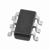
AP5100WG-7 Diodes Inc, AP5100WG-7 Datasheet

AP5100WG-7
Specifications of AP5100WG-7
Available stocks
Related parts for AP5100WG-7
AP5100WG-7 Summary of contents
Page 1
... Pin Assignments ( Top View ) 1 BST 2 GND 3 FB SOT26 Applications • Distributed Power Systems • Battery Charger • Pre-Regulator for Linear Regulators • WLED Drivers BST AP5100 OFF GND Figure 2. Typical Application Circuit www.diodes.com AP5100 Frequency OUT November 2010 © Diodes Incorporated ...
Page 2
... BST C3 L1 10nF 10µ AP5100 SW 1N5819HW-7 - Vout 3 GND ohm 200Kohm 1% Figure 4. White LED Driver Application www.diodes.com AP5100 Frequency L1 3.3µ 49.9kohm 100pF C2 22µF R2 6.3V 16.2kohm C2 10µF - Vout 16V Vout November 2010 © Diodes Incorporated OUT LED1 LED 2 LED 3 ...
Page 3
... Switch Output. This is the reference for the floating top gate driver. Functional Block Diagram AP5100 Document number: DS32130 Rev 1.2A Step-Down Converter with 1.4MHz Switching Description range from 0.1uF to 1uF. BST Figure 5. Functional Block Diagram www.diodes.com AP5100 Frequency . IN November 2010 © Diodes Incorporated ...
Page 4
... Min Typ. Max Unit 0.790 0.810 0.830 V 0.1 µA Ω 0.35 10 µA 2.4 A 1.1 1.4 1.7 MHz 480 kHz 87 % 100 ns 3.8 4.0 4.2 V 150 mV 0.4 V 1.2 V 0.3 µA 0.1 0.1 1.0 µA 0.4 1.0 mA 140 °C November 2010 © Diodes Incorporated ...
Page 5
... C, unless otherwise noted. A Load Transient Test (I =0.2A to 0.8A. Step at 0.8A/us) OUT Time- 100us/div Start-up through Enable (I =1A, resistive load) OUT Time- 50us/div Shutdown Through Enable (I =1A, resistive load) OUT Time- 50us/div www.diodes.com AP5100 Frequency November 2010 © Diodes Incorporated ...
Page 6
... ⎝ ⎠ 0.81 Equation 1 (V) R (kΩ) R (kΩ 80.6 (1%) 64.9 (1%) 49.9 (1%) 23.7 (1%) 49.9 (1%) 16.2 (1%) 49.9 (1%) 9.53 (1%) Output Voltages × − OUT IN OUT = L × × Δ Equation 2 is the inductor ripple current. November 2010 © Diodes Incorporated ...
Page 7
... UVLO fault www.diodes.com AP5100 Frequency = × ΔI Vout ESR capacitor inductor V OUT = − × × 0.3V diode out V IN Equation 5 5V BOOST DIODE 1 BST AP5100 10nF 6 SW Figure 6. External Bootstrap Diode November 2010 © Diodes Incorporated ...
Page 8
... These interconnecting impedances should be minimized by using wide, short printed circuit traces. The input capacitor needs close as possible to the IN and GND pins. The external feedback resistors should be placed next to the FB pin www.diodes.com AP5100 Frequency November 2010 © Diodes Incorporated ...
Page 9
... Ordering Information Package W : SOT26 Package Device Code AP5100WG-7 W Note: 6. Pad layout as shown on Diodes Inc. suggested pad layout document AP02001, which can be found on our website at http://www.diodes.com/datasheets/ap02001.pdf. Marking Information SOT26 Part Number AP5100W Package Outline Dimensions SOT26 AP5100 Document number: DS32130 Rev ...
Page 10
... Any Customer or user of this document or products described herein in such applications shall assume all risks of such use and will agree to hold Diodes Incorporated and all the companies whose products are represented on Diodes Incorporated website, harmless against all damages. ...


