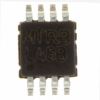
LP2975IMM-5.0/NOPB National Semiconductor, LP2975IMM-5.0/NOPB Datasheet - Page 17

LP2975IMM-5.0/NOPB
Manufacturer Part Number
LP2975IMM-5.0/NOPB
Description
IC DVR/CTRLR MOSFET LDO 8-MSOP
Manufacturer
National Semiconductor
Type
Positive Fixedr
Datasheet
1.LP2975IMM-5.0NOPB.pdf
(20 pages)
Specifications of LP2975IMM-5.0/NOPB
Number Of Outputs
1
Voltage - Output
5V
Current - Supply
180µA
Voltage - Input
1.8 ~ 24 V
Operating Temperature
-40°C ~ 125°C
Package / Case
8-MSOP, Micro8™, 8-uMAX, 8-uSOP,
Lead Free Status / RoHS Status
Lead free / RoHS Compliant
Other names
LP2975IMM-5.0
LP2975IMM-5.0TR
LP2975IMM-5.0TR
Available stocks
Company
Part Number
Manufacturer
Quantity
Price
Part Number:
LP2975IMM-5.0/NOPB
Manufacturer:
NS/国半
Quantity:
20 000
Application Hints
tributions of phase lag and lead from each one. As shown in
the graphs, most of the phase lag (or lead) contributed by a
pole (or zero) occurs within one decade of the frequency of
the pole (or zero).
In general, a phase margin (defined as the difference be-
tween the total phase shift and −180˚) of at least 20˚ to 30˚
is required for a stable loop.
Stability Analysis of Typical Applications
The first application to be analyzed is a fixed-output voltage
regulator with no feed-forward capacitor (see graph STABLE
PLOT WITHOUT FEED-FORWARD).
In this example, the value of C
pole formed by C
at 200 Hz. The ESR of C
by the ESR and C
selections follow the general guidelines stated previously in
this document). Note that the gate capacitance is assumed
to be moderate, with the pole formed by the C
as f
To estimate the total phase margin, the individual phase shift
contributions of each pole and zero will be calculated assum-
ing f
Controller pole shift = −90˚
f
f
p
z
shift = arctan (10k/5k) = +63˚
shift = −arctan (10k/200) = −89˚
pg
p
) occurring at 100 kHz.
= 200 Hz, f
Stable Plot without Feed-Forward
OUT
Effects of a Single Zero
z
OUT
= 5 kHz, f
and R
(defined as f
OUT
L
(previously defined as f
c
is selected so that zero formed
= 10 kHz and f
(Continued)
OUT
z
) is set at 5 kHz (these
is selected so that the
10003427
pg
GATE
10003426
= 100 kHz:
(defined
p
) is set
17
f
Summing the four numbers, the estimate for the total phase
shift is −122˚, which corresponds to a phase margin of 58˚.
This application is stable, but could be improved by using a
feed-forward capacitor (see next section).
EFFECT OF FEED-FORWARD: The example previously
used will be continued with the addition of a feed-forward
capacitor C
WITH FEED-FORWARD). The zero formed by C
ously defined as f
C
f
To estimate the total phase margin, the individual phase shift
contributions of each pole and zero will be calculated assum-
ing f
f
Controller pole shift = −90˚
f
f
f
f
f
Summing the six numbers, the estimate for the total phase
shift is −95˚, which corresponds to a phase margin of 85˚
(a 27˚ improvement over the same application without the
feed-forward capacitor).
For this reason, a feed-forward capacitor is recommended in
all applications. Although not always required, the added
phase margin typically gives faster settling times and pro-
vides some design guard band against C
tions with temperature.
Causes and Cures of Oscillations
The most common cause of oscillations in an LDO applica-
tion is the output capacitor ESR. If the ESR is too high or too
low, the zero (f
HIGH ESR: To illustrate the effect of an output capacitor with
high ESR, the previous example will be repeated except that
the ESR will be increased by a factor of 20X. This will cause
the frequency of the zero f
moves it from 5 kHz down to 250 Hz (see graph HIGH ESR
UNSTABLE WITHOUT FEED-FORWARD).
pg
pf
c
p
z
zf
pf
pg
F
/f
= 50 kHz, and f
shift = −arctan (50k/200) = −90˚
shift = arctan (50k/5k) = +84˚
shift = arctan (50k/100k) = +79˚
shift = −arctan (50k/40k) = −51˚
(previously defined as f
shift = −arctan (10k/100k) = −6˚
zf
shift = −arctan (50k/100k) = −27˚
p
corresponds to V
Improved Phase Margin with Feed-Forward
= 200 Hz, f
F
(see graph IMPROVED PHASE MARGIN
z
) does not provide enough phase lead.
zf
pg
) is set at 10 kHz and the pole formed by
z
= 100 kHz:
= 5 kHz, f
OUT
pf
= 5V).
) is set at 40 kHz (the 4X ratio of
z
to decrease by 20X, which
zf
= 10 kHz, f
OUT
and ESR varia-
10003428
pf
www.national.com
= 40 kHz,
F
(previ-


