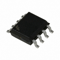
KA431DTF Fairchild Semiconductor, KA431DTF Datasheet

KA431DTF
Specifications of KA431DTF
Available stocks
Related parts for KA431DTF
KA431DTF Summary of contents
Page 1
... Operating Temperature Range • Low Output Noise Voltage • Fast Turn-on Response Internal Block Diagram REFERENCE REFERENCE (R) ©2011 Fairchild Semiconductor Corporation Description The KA431/KA431A/KA431L are three-terminal adjustable Ω Typical regulator series with a guaranteed thermal stability over applicable temperature ranges. The output voltage may be set to any value between VREF (approximately 2 ...
Page 2
KA431/KA431A/KA431L Absolute Maximum Ratings (Operating temperature range applies unless otherwise specified.) Parameter Cathode Voltage Cathode Current Range (Continuous) Reference Input Current Range Power Dissipation D, Z Suffix Package DIP Package Operating Temperature Range Junction Temperature Storage Temperature Range Recommended Operating ...
Page 3
Electrical Characteristics (T = +25°C, unless otherwise specified) A Parameter Symbol Conditions Reference Input REF Voltage I =10mA KA Deviation of ΔVREF/ Reference VKA=VREF, ΔT Input Voltage IKA=10mA Over- TMIN≤TA≤TMAX Temperature Ratio of Change in Reference ΔVREF/ ...
Page 4
KA431/KA431A/KA431L Test Circuits Figure 1. Test Circuit for V Figure 3. Test Circuit for REF KA(OFF) ≥V Figure 2. Test Circuit for V KA REF ...
Page 5
Typical Performance Characteristics Figure 4. Cathode Current vs. Cathode Voltage Figure 6. Change In Reference Input Voltage vs. Cathode Voltage Figure 8. Small Signal Voltage Amplification vs. Frequency KA431/KA431A/KA431L Figure 5. Cathode Current vs. Cathode Voltage Figure7. Dynamic Impedance Frequency ...
Page 6
KA431/KA431A/KA431L Typical Performance Characteristics 140 Vref 120 5 100 ...
Page 7
Typical Application R ⎛ ⎞ ------ - = + ⎝ ⎠ O ref R 2 Figure 11. Shunt Regulator Figure 14. Current Limit or Current Source R ⎛ ⎞ 1 ------ - ...
Page 8
KA431/KA431A/KA431L Mechanical Dimensions Package 4.58 ±0.10 0.46 1.27TYP ±0.20 [1.27 ] 3.60 8 TO-92 Bulk Type +0.25 –0.15 1.27TYP ±0.20 [1.27 ] ±0.20 (R2.29) Dimensions in millimeters +0.10 0.38 –0.05 ...
Page 9
Mechanical Dimensions Package TO-92 Ammo Type & Tape And Reel Type (Continued) KA431/KA431A/KA431L Dimensions in millimeters 9 ...
Page 10
KA431/KA431A/KA431L Mechanical Dimensions Package ±0.20 6.40 0.252 ±0.008 #1 #4 7.62 0.300 10 (Continued) 8-DIP #8 #5 5.08 MAX 0.200 3.40 ±0.20 ±0.008 0.134 Dimensions in millimeters ±0.30 3.30 0.130 ±0.012 0.33 MIN 0.013 ...
Page 11
Mechanical Dimensions Package #1 #4 0.156 0.50 ±0.20 ±0.008 0.020 (Continued) 8-SOP ±0.20 1.55 ±0.008 0.061 #8 #5 6.00 ±0.30 1.80 MAX ±0.012 0.236 0.071 ±0.20 3.95 ±0.008 5.72 0.225 KA431/KA431A/KA431L Dimensions in millimeters 0.1~0.25 MIN 0.004~0.001 11 ...
Page 12
... DISCLAIMER FAIRCHILD SEMICONDUCTOR RESERVES THE RIGHT TO MAKE CHANGES WITHOUT FURTHER NOTICE TO ANY PRODUCTS HEREIN TO IMPROVE RELIABILITY, FUNCTION OR DESIGN. FAIRCHILD DOES NOT ASSUME ANY LIABILITY ARISING OUT OF THE APPLICATION OR USE OF ANY PRODUCT OR CIRCUIT DESCRIBED HEREIN; NEITHER DOES IT CONVEY ANY LICENSE UNDER ITS PATENT RIGHTS, NOR THE RIGHTS OF OTHERS ...


