LM336BZ-5.0/NOPB National Semiconductor, LM336BZ-5.0/NOPB Datasheet - Page 3
LM336BZ-5.0/NOPB
Manufacturer Part Number
LM336BZ-5.0/NOPB
Description
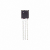
IC REFERENCE DIODE 5V TO92-3
Manufacturer
National Semiconductor
Type
Voltage Referencer
Specifications of LM336BZ-5.0/NOPB
Reference Type
Shunt
Voltage - Output
5V
Tolerance
±2%
Number Of Channels
1
Current - Cathode
600µA
Current - Output
10mA
Operating Temperature
0°C ~ 70°C
Mounting Type
Through Hole
Package / Case
TO-92-3 (Standard Body), TO-226
Current, Supply
600 μA to 10 mA
Package Type
TO-92
Regulator Type
Shunt
Temperature, Operating, Range
0 to +70 °C
Voltage, Breakdown, Reverse
5 V
Lead Free Status / RoHS Status
Lead free / RoHS Compliant
Voltage - Input
-
Temperature Coefficient
-
Current - Quiescent
-
Lead Free Status / Rohs Status
RoHS Compliant part
Electrostatic Device
Other names
*LM336BZ-5.0
*LM336BZ-5.0/NOPB
LM336BZ-5.0
*LM336BZ-5.0/NOPB
LM336BZ-5.0


Reverse Breakdown
Voltage
Reverse Breakdown
Change
With Current
Reverse Dynamic
Impedance
Temperature Stability V
(Note 4)
Reverse Breakdown
Change
With Current
Adjustment Range
Reverse Dynamic
Impedance
Long Term Stability
Absolute Maximum Ratings
If Military/Aerospace specified devices are required,
please contact the National Semiconductor Sales Office/
Distributors for availability and specifications.
Electrical Characteristics
(Note 3)
Note 1: Absolute Maximum Ratings indicate limits beyond which damage to the device may occur. Electrical specifications do not apply when operating the device
beyond its specified operating conditions.
Note 2: For elevated temperature operation, T
Note 3: Unless otherwise specified, the LM136-5.0 is specified from −55°C
C
Note 4: Temperature stability for the LM336 and LM236 family is guaranteed by design. Design limits are guaranteed (but not 100% percent production tested)
over the indicated temperature and supply voltage ranges. These limits are not used to calculate outgoing quality levels. Stability is defined as the maximum
charge in V
Reverse Current
Forward Current
Storage Temperature
Operating Temperature Range (Note 2)
≤
T
LM136-5.0
LM236-5.0
Parameter
A
≤
LM136
LM236
LM336
+70°C.
REF
from 25°C to T
150°C
125°C
100°C
T
LM136-5.0/LM236-5.0/LM336-5.0
LM136A-5.0/LM236A-5.0, LM336B-5.0
T
600 μA
T
I
0°C
−25°C
−55°C
600 μA
Circuit of Figure 1
I
T
R
R
A
A
A
A
R
=1 mA, (Figure 2)
=25°C, I
=25°C,
=25°C, I
= 1 mA
=25°C±0.1°C, I
Adjusted 5.00V
A
≤
(min) or T
θ
θ
T
≤
≤
ja
ja
A
≤
≤
≤
T
T
Thermal Resistance
(Junction to Ambient)
(Junction to Case)
I
I
A
A
R
70°C (LM336-5.0)
R
≤
≤
≤
≤
R
R
=1 mA
=1 mA, f = 100 Hz
+85°C (LM236-5.0)
+125°C (LM136-5.0)
10 mA
10 mA
A
(max).
Conditions
j
max is:
R
=1 mA, t = 1000 hrs
−60°C to +150°C
−55°C to +150°C
−25°C to +85°C
(Note 1)
15mA
10mA
180°C/W (0.4 Leads)
170°C/W (0.125 Leads)
N/A
≤
T
A
TO-92
3
LM136A-5.0/LM236A-5.0
≤
4.95
Min
4.9
LM136-5.0/LM236-5.0
+125°C, the LM236-5.0 from −25°C
See AN-450 “Surface Mounting Methods and Their Effect on
Product Reliability” (appendix D) for other methods of solder-
ing surface mount devices.
Soldering Information
LM336-5.0
TO-92 Package (10 sec.)
TO-46 Package (10 sec.)
SO Package
Vapor Phase (60 sec.)
Infrared (15 sec.)
5.00
5.00
Typ
0.6
0.8
20
±1
20
6
7
6
440°C/W 165°C/W
TO-46
80°C/W
Max
5.05
5.1
1.2
1.6
12
18
36
17
SO-8
≤
4.90
Min
N/A
4.8
T
A
≤
+85°C and the LM336-5.0 from 0°
LM336B-5.0
LM336-5.0
5.00
5.00
Typ
0.6
0.8
±1
20
6
4
6
0°C to +70°C
Max
5.2
5.1
2.5
20
12
24
www.national.com
2
260°C
300°C
215°C
220°C
Units
ppm
mV
mV
mV
mV
mV
Ω
Ω
V
V
V
Related parts for LM336BZ-5.0/NOPB
Image
Part Number
Description
Manufacturer
Datasheet
Request
R

Part Number:
Description:
Voltage Reference
Manufacturer:
National Semiconductor
Datasheet:

Part Number:
Description:
Voltage & Current References REORDER 511-LM336Z
Manufacturer:
STMicroelectronics
Datasheet:

Part Number:
Description:
IC REFERENCE DIODE 2.5V TO92-3
Manufacturer:
National Semiconductor
Datasheet:
Part Number:
Description:
IC, SHUNT V-REF, DIODE2.5V, 1%, TO-92
Manufacturer:
National Semiconductor
Datasheet:

Part Number:
Description:
Regulator, Shunt, Fixed, 2.5V Output
Manufacturer:
STMicroelectronics
Datasheet:

Part Number:
Description:
National Semiconductor [8-Bit D/A Converter]
Manufacturer:
National Semiconductor
Datasheet:
Part Number:
Description:
National Semiconductor [Media Coprocessor]
Manufacturer:
National Semiconductor
Datasheet:
Part Number:
Description:
Digitally Controlled Tone and Volume Circuit with Stereo Audio Power Amplifier, Microphone Preamp Stage and National 3D Sound
Manufacturer:
National Semiconductor
Datasheet:
Part Number:
Description:
Digitally Controlled Tone and Volume Circuit with Stereo Audio Power Amplifier, Microphone Preamp Stage and National 3D Sound
Manufacturer:
National Semiconductor
Datasheet: