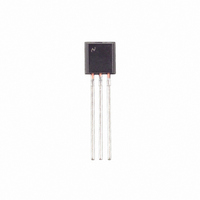
LM336BZ-5.0/NOPB National Semiconductor, LM336BZ-5.0/NOPB Datasheet - Page 2

LM336BZ-5.0/NOPB
Manufacturer Part Number
LM336BZ-5.0/NOPB
Description
IC REFERENCE DIODE 5V TO92-3
Manufacturer
National Semiconductor
Type
Voltage Referencer
Specifications of LM336BZ-5.0/NOPB
Reference Type
Shunt
Voltage - Output
5V
Tolerance
±2%
Number Of Channels
1
Current - Cathode
600µA
Current - Output
10mA
Operating Temperature
0°C ~ 70°C
Mounting Type
Through Hole
Package / Case
TO-92-3 (Standard Body), TO-226
Current, Supply
600 μA to 10 mA
Package Type
TO-92
Regulator Type
Shunt
Temperature, Operating, Range
0 to +70 °C
Voltage, Breakdown, Reverse
5 V
Lead Free Status / RoHS Status
Lead free / RoHS Compliant
Voltage - Input
-
Temperature Coefficient
-
Current - Quiescent
-
Lead Free Status / Rohs Status
RoHS Compliant part
Electrostatic Device
Other names
*LM336BZ-5.0
*LM336BZ-5.0/NOPB
LM336BZ-5.0
*LM336BZ-5.0/NOPB
LM336BZ-5.0
Reverse Breakdown Voltage
Reverse Breakdown Change
With Current
Reverse Dynamic Impedance
Temperature Stability
(Note 4)
Reverse Breakdown Change
With Current
Adjustment Range
Reverse Dynamic Impedance
Long Term Stability
Absolute Maximum Ratings
If Military/Aerospace specified devices are required,
please contact the National Semiconductor Sales Office/
Distributors for availability and specifications.
Electrical Characteristics
(Note 3)
Note 1: Absolute Maximum Ratings indicate limits beyond which damage to the device may occur. Electrical specifications do not apply when operating the device
beyond its specified operating conditions.
Note 2: For elevated temperature operation, T
Note 3: Unless otherwise specified, the LM136-5.0 is specified from −55˚C≤T
0˚C≤T
Note 4: Temperature stability for the LM336 and LM236 family is guaranteed by design. Design limits are guaranteed (but not 100% percent production tested) over
the indicated temperature and supply voltage ranges. These limits are not used to calculate outgoing quality levels. Stability is defined as the maximum charge in
V
Reverse Current
Forward Current
Storage Temperature
Operating Temperature Range (Note 2)
REF
LM136-5.0
LM236-5.0
from 25˚C to T
A
LM136
LM236
LM336
≤+70˚C.
Parameter
150˚C
125˚C
100˚C
A
(min) or T
A
θ
θ
(max).
ja
ja
Thermal Resistance
(Junction to Ambient)
(Junction to Case)
T
LM136-5.0/LM236-5.0/LM336-5.0
LM136A-5.0/LM236A-5.0, LM336B-5.0
T
600 µA≤I
T
V
I
0˚C≤T
−25˚C≤T
−55˚C≤T
600 µA≤I
Circuit of Figure 1
I
T
R
R
A
A
A
R
A
=1 mA, (Figure 2)
=25˚C, I
=25˚C,
=25˚C, I
=25˚C
= 1 mA
Adjusted 5.00V
A
j
max is:
≤70˚C (LM336-5.0)
A
A
±
R
R
≤+85˚C (LM236-5.0)
≤+125˚C (LM136-5.0)
≤10 mA
≤10 mA
0.1˚C, I
R
R
−60˚C to +150˚C
−55˚C to +150˚C
=1 mA
=1 mA, f = 100 Hz
−25˚C to +85˚C
Conditions
(Note 1)
R
=1 mA, t = 1000 hrs
15mA
10mA
180˚C/W (0.4" Leads)
170˚C/W (0.125"
Leads)
N/A
TO-92
3
A
≤+125˚C, the LM236-5.0 from −25˚C≤T
See AN-450 “Surface Mounting Methods and Their Effect on
Product Reliability” (appendix D) for other methods of sol-
dering surface mount devices.
Soldering Information
LM336-5.0
TO-92 Package (10 sec.)
TO-46 Package (10 sec.)
SO Package
Vapor Phase (60 sec.)
Infrared (15 sec.)
LM136A-5.0/LM236A-5.0
LM136-5.0/LM236-5.0
4.95
Min
4.9
440˚C/W 165˚C/W
TO-46
80˚C/W
5.00
5.00
Typ
0.6
0.8
±
20
20
6
7
6
1
Max
5.05
SO-8
5.1
1.2
1.6
N/A
12
18
36
17
A
≤+85˚C and the LM336-5.0 from
4.90
Min
4.8
LM336B-5.0
LM336-5.0
5.00
5.00
Typ
0.6
0.8
±
20
6
4
6
1
0˚C to +70˚C
Max
5.2
5.1
2.5
20
12
24
2
260˚C
300˚C
215˚C
220˚C
Units
ppm
mV
mV
mV
mV
mV
Ω
Ω
V
V
V


