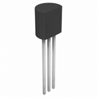
TL431AILP Microsemi Analog Mixed Signal Group, TL431AILP Datasheet - Page 11

TL431AILP
Manufacturer Part Number
TL431AILP
Description
IC REFERENCE PROG PREC TO92
Manufacturer
Microsemi Analog Mixed Signal Group
Datasheet
1.TL431IDM.pdf
(11 pages)
Specifications of TL431AILP
Reference Type
Shunt, Adjustable
Voltage - Output
2.5 ~ 36 V
Tolerance
±1%
Temperature Coefficient
30ppm/°C
Number Of Channels
1
Current - Cathode
400µA
Current - Output
100mA
Operating Temperature
-40°C ~ 85°C
Mounting Type
Through Hole
Package / Case
TO-92-3 (Standard Body), TO-226
Lead Free Status / RoHS Status
Lead free / RoHS Compliant
Voltage - Input
-
Current - Quiescent
-
Other names
TL431AILPR
Available stocks
Company
Part Number
Manufacturer
Quantity
Price
Company:
Part Number:
TL431AILP
Manufacturer:
TI
Quantity:
10 000
Company:
Part Number:
TL431AILP
Manufacturer:
SEIKO
Quantity:
2 300
Company:
Part Number:
TL431AILPG
Manufacturer:
STM
Quantity:
6 672
Company:
Part Number:
TL431AILPM
Manufacturer:
TI
Quantity:
50 210
Company:
Part Number:
TL431AILPR
Manufacturer:
Texas Instruments
Quantity:
20 000
Part Number:
TL431AILPR
Manufacturer:
TI/德州仪器
Quantity:
20 000
Copyright © 1999
Rev. 1.4, 2006-09-26
Note: R should provide > 1mA cathode current to the TL431/A & TL1431 at
Note: R3 and R4 are selected to provide the desired LED intensity and > 1mA
cathode current to the TL431/A & TL431B at the available V+
minimum V
TM
LED on when Low Limit < V
12V
Figure 18 – High Current Shunt Regulator
V
R1A
R2A
BATT
BATT
V
BATT
Figure 16 – Shunt Regulator
Low
High
Figure 20 – Voltage Monitor
TL431/A
& TL431B
V
V
Limit
Limit
O
R (see Note)
O
11861 Western Avenue, Garden Grove, CA. 92841, 714-898-8121, Fax: 714-893-2570
V
=
RE F
=
R1
R2
⎛
⎜
⎝
⎛
⎜
⎝
R1 0.1%
R2 0.1%
1
=
=
1
+
⎛
⎜
⎝
+
⎛
⎜
⎝
1
1
R1
R2
R2
R1
+
+
R1B
R2B
⎞
⎟
⎠
R1B
R2B
⎞
⎟
⎠
TL431/A
& TL431B
•
•
R2B
BATT
V
V
I
K
(Note)
⎞
⎟
⎠
TL431/A
& TL431 B
REF
⎞
⎟
⎠
R3 (see Note)
REF
•
•
A P P L I C A T I O N I N F O R M A T I O N
R4
< High Limit
V
V
V
REF
REF
O
Integrated Products Division
V
O
®
Microsemi
Figure 17 – Single-Supply Comparator with Temperature-
Note: Refer to the stability boundary conditions in Figure 15 to determine
Precision programmable References
allowable values for C.
V
BATT
Figure 21 – Precision Contact – Current Sink
Compensated Threshold
Input
P
TL431/A
& TL431B
RODUCTION
Figure 19 – Crowbar Circuit
R1
R2
TL431 / TL431A / TL431B
TL431/A
& TL431B
TL431/A
& TL431B
V
BATT
D
ATA
V
BATT
S
HEET
V
V
(see Note)
V
ON
OFF
GND
C
O
R
0.1%
I
S
O
2V
V
BAT T
V
O
Page 11


