AD537KD Analog Devices Inc, AD537KD Datasheet - Page 8
AD537KD
Manufacturer Part Number
AD537KD
Description
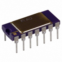
IC V/F CONV 14-CDIP
Manufacturer
Analog Devices Inc
Type
Voltage to Frequencyr
Datasheet
1.AD537JH.pdf
(8 pages)
Specifications of AD537KD
Rohs Status
RoHS non-compliant
Frequency - Max
100kHz
Full Scale
±30ppm/°C
Linearity
±0.05%
Mounting Type
Through Hole
Package / Case
14-CDIP (0.300", 7.62mm)
Frequency
150kHz
Full Scale Range
0kHz To 150kHz
Linearity %
0.15%
Supply Voltage Range
4.5V To 36V
Digital Ic Case Style
TO-116
No. Of Pins
14
Msl
MSL 1 - Unlimited
Converter Function
VFC
Full Scale Frequency
150
Power Supply Requirement
Single/Dual
Single Supply Voltage (typ)
5/9/12/15/18/24/28V
Single Supply Voltage (max)
36V
Single Supply Voltage (min)
4.5V
Dual Supply Voltage (typ)
±9/±12/±15V
Dual Supply Voltage (min)
±5V
Dual Supply Voltage (max)
±18V
Operating Temperature (min)
0C
Operating Temperature (max)
70C
Operating Temperature Classification
Commercial
Package Type
SBCDIP
Lead Free Status / Rohs Status
Not Compliant
Available stocks
Company
Part Number
Manufacturer
Quantity
Price


AD537
THERMOCOUPLE INPUT
The output of a Chromel-Constantan (Type E) thermocouple,
using a reference junction at 0°C, varies from 0 mV to 53.14 mV
over the temperature range 0°C to +700°C with a slope of
80.678 µV/degree over most of its range and some nonlinearity
over the range 0°C to +200°C. For this example, we assume
that it is desired to indicate temperature in Degrees Celsius
using a counter/display with a 100 ms gate width. Thus, the V-F
converter must deliver an output of 7 kHz for an input of
53.14 mV. If very precise operation down to 0°C is imperative,
some sort of linearizing is necessary (see, for example, Analog
Devices’ Nonlinear Circuits Handbook, pp. 92–97) but in many
cases operation is only needed over part of the range.
The circuit shown in Figure 14 provides good accuracy from
+300°C to +700°C. The extrapolation of the temperature volt-
age curve back to 0°C shows that an offset of –3.34 mV is
required to fit the curve most exactly. This small amount of
voltage can be introduced without an additional calibration step
using the +1.00 V output of the AD537. To adjust the scale, the
thermocouple should be raised to a known reference tempera-
ture near 500°C and the frequency adjusted to value using R1.
The error should be within ± 0.2% over the range 400°C to
700°C.
T
MEAS
T
(0
REF
°
C)
Linearization
Figure 14. Thermocouple Interface with First-Order
0 TO 53mV
R1 SCALE
360µA
50
F
S
I
OFFSET
≈ 21µA
120
47k
2
3
4
5
6
7
1
V
V
T
R
BUF
REFERENCE
PRECISION
VOLTAGE
TO-FREQ
DRIVER
CURR-
CONV
AD537
14
13
12
11
10
9
8
+5V
V
LOGIC
10Hz/
0.005µF
°
C
–8–
0.370 (9.40)
0.335 (8.51)
0.355 (9.02)
0.305 (7.75)
0.200 (5.08)
0.125 (3.18)
(5.08)
0.200
MAX
PIN 1
0.005 (0.13) MIN
14-Lead Side-Brazed Ceramic DIP (TO–116)
0.044 (1.12)
0.032 (0.81)
0.023 (0.58)
0.014 (0.36)
0.040 (1.01)
0.010 (0.25)
0.185 (4.70)
0.165 (4.19)
14
1
(1.27)
0.050
MAX
Dimensions shown in inches and (mm).
10-Lead Metal Can (TO-100)
OUTLINE DIMENSIONS
0.785 (19.94) MAX
0.100
(2.54)
BSC
0.562 (14.30)
0.500 (12.70)
REFERENCE PLANE
0.019 (0.48)
0.016 (0.41)
BASE & SEATING PLANE
0.021 (0.53)
0.016 (0.41)
(H-10A)
(D–14)
0.070 (1.78)
0.030 (0.76)
0.098 (2.49) MAX
0.230
(5.84)
BSC
8
7
(2.92)
0.115
BSC
SEATING
PLANE
0.310 (7.87)
0.220 (5.59)
0.060 (1.52)
0.015 (0.38)
4
3
0.150
(3.81)
MIN
5
2
1
6
0.034 (0.86)
0.028 (0.71)
0.015 (0.38)
0.008 (0.20)
0.320 (8.13)
0.290 (7.37)
10
7
BSC
36
8
9
°
0.045 (1.14)
0.029 (0.74)
REV. C
Related parts for AD537KD
Image
Part Number
Description
Manufacturer
Datasheet
Request
R

Part Number:
Description:
±1.7g Dual-Axis IMEMS Accelerometer Evaluation Board
Manufacturer:
Analog Devices Inc
Datasheet:

Part Number:
Description:
Inertial Sensor Evaluation System
Manufacturer:
Analog Devices Inc
Datasheet:
Part Number:
Description:
Manufacturer:
Analog Devices Inc
Datasheet:
Part Number:
Description:
Manufacturer:
Analog Devices Inc
Datasheet:
Part Number:
Description:
Manufacturer:
Analog Devices Inc
Datasheet:
Part Number:
Description:
Manufacturer:
Analog Devices Inc
Datasheet:
Part Number:
Description:
Manufacturer:
Analog Devices Inc
Datasheet:
Part Number:
Description:
Manufacturer:
Analog Devices Inc
Datasheet:
Part Number:
Description:
Manufacturer:
Analog Devices Inc
Datasheet:
Part Number:
Description:
Manufacturer:
Analog Devices Inc
Datasheet:
Part Number:
Description:
Manufacturer:
Analog Devices Inc
Datasheet:
Part Number:
Description:
Manufacturer:
Analog Devices Inc
Datasheet:
Part Number:
Description:
Manufacturer:
Analog Devices Inc
Datasheet: