AD652JP Analog Devices Inc, AD652JP Datasheet - Page 24
AD652JP
Manufacturer Part Number
AD652JP
Description
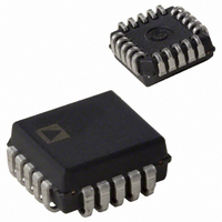
IC V-F CONV SYNCH MONO 5V 20PLCC
Manufacturer
Analog Devices Inc
Type
Voltage to Frequencyr
Datasheet
1.AD652JPZ.pdf
(28 pages)
Specifications of AD652JP
Rohs Status
RoHS non-compliant
Frequency - Max
2MHz
Full Scale
±25ppm/°C
Linearity
±0.005%
Mounting Type
Surface Mount
Package / Case
20-LCC (J-Lead)
Converter Function
VFC
Full Scale Frequency
2000
Power Supply Requirement
Single/Dual
Single Supply Voltage (max)
36V
Single Supply Voltage (min)
12V
Dual Supply Voltage (typ)
±15V
Dual Supply Voltage (min)
±6V
Dual Supply Voltage (max)
±18V
Operating Temperature (min)
0C
Operating Temperature (max)
70C
Operating Temperature Classification
Commercial
Package Type
PLCC
Lead Free Status / Rohs Status
Not Compliant
Available stocks
Company
Part Number
Manufacturer
Quantity
Price

Part Number:
AD652JP
Manufacturer:
ADI/亚德诺
Quantity:
20 000
Company:
Part Number:
AD652JP-REEL
Manufacturer:
Analog Devices Inc
Quantity:
10 000
Company:
Part Number:
AD652JP-REEL7
Manufacturer:
Analog Devices Inc
Quantity:
10 000
Part Number:
AD652JPZ
Manufacturer:
ADI/亚德诺
Quantity:
20 000


AD652
BRIDGE TRANSDUCER INTERFACE
The circuit of Figure 38 illustrates a simple interface between
the AD652 and a bridge-type transducer. The AD652 is an ideal
choice because its buffered 5 V reference can be used as the
bridge excitation, thereby ratiometrically eliminating the gain
drift related errors. This reference provides a minimum of
10 mA of external current, which is adequate for bridge
resistance of 600 Ω and above. If, for example, the bridge
resistance is 120 Ω or 350 Ω, an external pull-up resistor ( R
required. R
An instrumentation amplifier is used to condition the bridge
signal before presenting it to the SVFC. With its high CMRR,
the AD652 minimizes common-mode errors and can be set to
arbitrary gains between 1 and 10,000 via three resistors,
simplifying the scaling for the part’s calibrated 10 V input range.
R
PU
PU
(max)
NOTES
1. R
2. R
3. S1 IN POSITION 1 FOR UNIPOLAR SIGNALS
and can be calculated using the following formula:
AND POSITION 2 FOR BIPOLAR SIGNALS.
F
PU
SHOULD BE BETWEEN 10kΩ AND 20kΩ.
NEEDED IF R
=
R
BRIDGE
5
+
V
V
BRIDGE
S
R
V
–
BRIDGE
BRIDGE
−
−
5
10
V
+
600Ω
mA
R
R
R
G
F
F
15
12
16
1
5
2
AD625
+15V
–15V
9
8
F
OUT
Figure 38. Bridge Transducer Interface
1
11
= V
7
BRIDGE
2
S1
10
PU
Rev. C | Page 24 of 28
) is
2R
R
R
C
G
PU
F
INT
+ 1
–15V
+15V
F
These resistors should be selected such that the following
equation holds:
where 10 kΩ ≤ R
voltage of the bridge.
The bridge output may be unipolar, as is the case for most
pressure transducers, or it may be bipolar as in some strain
measurements. If the signal is unipolar, the reference input of
the AD625 (Pin 7) is simply grounded. If the bridge has a
bipolar output, however, the AD652 reference can be tied to
Pin 7, thereby, converting a 5 V signal (after gain) into a 0 V to
+10 V input for the SVFC.
CLOCK
1
2
3
4
5
6
7
8
10V
20kΩ
SYNCHRONOUS
10
2
VOLTAGE-TO-
FREQUENCY
CONVERTER
AD652
V
1mA
=
V
BRIDGE
F
≤ 20 kΩ, and V
⎛
⎜
⎜
⎝
REFERENCE
AND
2
R
R
G
F
5V
+
D
SHOT
ONE
Q
Q
1
⎞
⎟
⎟
⎠
FLOP
"D"
CK
BRIDGE
16
15
14
13
12
11
10
9
is the maximum output
+15V
V
CLOCK IN
LOGIC
R
L
FREQ
OUT
Related parts for AD652JP
Image
Part Number
Description
Manufacturer
Datasheet
Request
R

Part Number:
Description:
±1.7g Dual-Axis IMEMS Accelerometer Evaluation Board
Manufacturer:
Analog Devices Inc
Datasheet:

Part Number:
Description:
Inertial Sensor Evaluation System
Manufacturer:
Analog Devices Inc
Datasheet:
Part Number:
Description:
Manufacturer:
Analog Devices Inc
Datasheet:
Part Number:
Description:
Manufacturer:
Analog Devices Inc
Datasheet:
Part Number:
Description:
Manufacturer:
Analog Devices Inc
Datasheet:
Part Number:
Description:
Manufacturer:
Analog Devices Inc
Datasheet:
Part Number:
Description:
Manufacturer:
Analog Devices Inc
Datasheet:
Part Number:
Description:
Manufacturer:
Analog Devices Inc
Datasheet:
Part Number:
Description:
Manufacturer:
Analog Devices Inc
Datasheet:
Part Number:
Description:
Manufacturer:
Analog Devices Inc
Datasheet:
Part Number:
Description:
Manufacturer:
Analog Devices Inc
Datasheet:
Part Number:
Description:
Manufacturer:
Analog Devices Inc
Datasheet:
Part Number:
Description:
Manufacturer:
Analog Devices Inc
Datasheet: