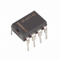
DS1621 Maxim Integrated Products, DS1621 Datasheet

DS1621
Specifications of DS1621
Available stocks
Related parts for DS1621
DS1621 Summary of contents
Page 1
... DIP or SO package (150mil and 208mil) DESCRIPTION The DS1621 Digital Thermometer and Thermostat provides 9-bit temperature readings, which indicate the temperature of the device. The thermal alarm output, T device exceeds a user-defined temperature TH. The output remains active until the temperature drops below user defined temperature TL, allowing for any hysteresis necessary ...
Page 2
... The temperature reading is provided in a 9-bit, two’s complement reading by issuing the READ TEMPERATURE command. Table 2 describes the exact relationship of output data to measured temperature. The data is transmitted through the 2-wire serial interface, MSB first. The DS1621 can measure temperature over the range of -55°C to +125°C in 0.5°C increments. ...
Page 3
... Figure 1. DS1621 FUNCTIONAL BLOCK DIAGRAM SCL ADDRESS AND SDA I/O CONTROL STATUS REGISTER & CONTROL LOGIC TEMPERATURE SENSOR HIGH TEMP TRIGGER, TH LOW TEMP TRIGGER, TL DIGITAL COMPARATOR/LOGIC OUT ...
Page 4
... COUNT_PER_C value. The higher resolution temperature may be then be calculated by the user using the following: TEMPERATURE=TEMP_READ-0.25 + The DS1621 always powers low power idle state, and the Start Convert T command must be used to initiate conversions. The DS1621 can be programmed to perform continuous consecutive conversions (continuous-conversion mode perform single conversions on command (one-shot mode) ...
Page 5
... Temperature High Flag. This bit will be set to “1” when the temperature is greater than or equal to the value of TH. It will remain “1” until reset by writing “0” into this location or removing power from the device. This feature provides a method of determining if the DS1621 has ever been subjected to temperatures above TH while power has been applied. ...
Page 6
... Temperature Low Flag. This bit will be set to “1” when the temperature is less than or equal to the value of TL. It will remain “1” until reset by writing “0” into this location or removing power from the device. This feature provides a method of determining if the DS1621 has ever been subjected to temperatures below TL while power has been applied. ...
Page 7
... Within the bus specifications a regular mode (100kHz clock rate) and a fast mode (400kHz clock rate) are defined. The DS1621 works in both modes. Acknowledge: Each receiving device, when addressed, is obliged to generate an acknowledge after the reception of each byte. The master device must generate an extra clock pulse which is associated with this acknowledge bit ...
Page 8
... A control byte is the first byte received following the START condition from the master device. The control byte consists of a 4-bit control code; for the DS1621, this is set as 1001 binary for read and write operations. The next 3 bits of the control byte are the device select bits (A2, A1, A0). They are used by the master device to select which of eight devices are to be accessed ...
Page 9
... Figure 5. 2-WIRE SERIAL COMMUNICATION WITH DS1621 ...
Page 10
... COMMAND SET Data and control information is read from and written to the DS1621 in the format shown in Figure 5. To write to the DS1621, the master will issue the slave address of the DS1621 and the R/ “0”. After receiving an acknowledge, the bus master provides a command protocol. After receiving this protocol, the DS1621 will issue an acknowledge and then the master may send data to the DS1621 ...
Page 11
... Table 3. DS1621 COMMAND SET INSTRUCTION DESCRIPTION TEMPERATURE CONVERSION COMMANDS Read Temperature Read last converted temperature value from temperature register. Read Counter Reads value of Count_Remain Read Slope Reads value of the Count_Per_C Start Convert T Initiates temperature conversion. Stop Convert T Halts temperature conversion. Access TH ...
Page 12
... MEMORY FUNCTION EXAMPLE Example: Bus master sets up DS1621 for continuous conversion and thermostatic function. BUS MASTER DS1621 MODE MODE DATA (MSB FIRST) START Bus Master initiates a START condition. <address,0> Bus Master sends DS1621 address; R/ ACK DS1621 generates acknowledge bit. ACh Bus Master sends Access Config command protocol. ...
Page 13
ABSOLUTE MAXIMUM RATINGS* Voltage on Any Pin Relative to Ground Operating Temperature Range Storage Temperature Range Soldering Temperature * This is a stress rating only and functional operation of the device at these or any other conditions above those indicated ...
Page 14
Active Supply I CC Current Standby Supply I STBY Current Thermostat Output Output V OUT OL Voltage Temperature Conversion -55°C to +85°C Temperature Conversion +85°C to +125° Write Communication Only 1 mA Source 2.4 ...
Page 15
AC ELECTRICAL CHARACTERISTICS PARAMETER SYMBOL Temperature T TC Conversion Time NV Write Cycle t WR Time SCL Clock f SCL Frequency Bus Free Time t BUF Between a STOP and START Condition Hold Time t HD:STA (Repeated) START Condition Low ...
Page 16
NOTES: 1. All voltages are referenced to ground. 2. I/O pins of fast mode devices must not obstruct the SDA and SCL lines specified with T pin open. CC OUT 4. I specified with V at ...


